Eng-Tips is the largest engineering community on the Internet

Intelligent Work Forums for Engineering Professionals

Miami Pedestrian Bridge, Part XIV 78

Status
Not open for further replies.

JAE

Structural
Jun 27, 2000
15,432
0
36
US
A continuation of our discussion of this failure. Best to read the other threads first to avoid rehashing things already discussed.

Part I
thread815-436595

Part II
thread815-436699

Part III
thread815-436802

Part IV
thread815-436924

Part V
thread815-437029

Part VI
thread815-438451

Part VII
thread815-438966

Part VIII
thread815-440072

Part IX
thread815-451175

Part X
thread815-454618

Part XI
thread815-454998

Part XII
thread815-455746

Part XIII
thread815-457935


Replies continue below

Recommended for you

Fred - As I read the article I thought it was written by FIGG. But deeper into it the criticism included FIGG.
The comments by the 'public' if you will provide an insight to what a jury might think/say/decide.
 
The conclusions and board member statement at the end of the report are very damning stuff. I'm a little surprised by how strong the verbiage is, but as others have mentioned since the NTSB meeting, it's clear they've been flabbergasted this failure was allowed to happen.

As an aside, who ultimately determines if the EOR loses their PE due to the miscalculations and apparent disregard for public safety? I assume it'd fall to the professional departments of the various states he's licensed in?
 
Like you, I have yet to identify where FIGG developed the lower design number for the connection of 11/12 members to the deck - the shear friction failure location. NTSB suggests they did not correctly interpret the results of the computer models.
There is a hand calculation in the FIGG design calcs that addresses node 1/2 using a "punch thru" set of shear planes thru the deck and out the end. I do not see a similar calc for node 11/12.
The slide presentation calc of the shear in node 11/12 was a similar calculation to that at node 1/2 in the design calc. That calc and a subsequent calc presented to NTSB included contributions from any reinforcing which could be identified in the region, not being limited to reinforcing intended to resist shear friction.
The FIGG calcs were made using a coeff of friction of 1.0, while the actual joints had received no roughening and a correct coeff of friction would be 0.6, reducing the contribution of all components by 40%. The NTSB concluded the joint prep was not a factor - it would have failed anyway.
As I recall now, that slide presentation did not address the presence of two 4" dia pvc sleeves vertical thru the deck and together at both sides of member 12. Nor did it consider the extensive cracking of diaphragm 2, which it assessed as having cracked from the vertical component of members 11 and 12. The horizontal thrust was greater than the vertical component and the joint had slipped maybe 1/2 inch when the slide presentation was made. Tests from WJE show that maximum resistance of a shear friction joint is developed at a slip of 0.020 to 0.025 inches - long before the EOR saw the actual conditions on the morning of March 15. It was downhill from there.
You may have answered your own question. It appears that almost no attention was given to tne need for node 11/12 and member 11 to "stand alone" during Stage 2 erection and until the entire double span structure was completed.
When complete, member 12 was to be "wrapped" and integrated into a concrete pylon 5 feet by 6 feet in dimension cast with the north span. And the north span was a shortened mirror image of the main span, so member 14 of the north span counters part of the horizontal force in member 11 in the final structure. The mental image of the huge pylon seems to have created a confidence in this area that overshadowed the importance of capacity at Stage 2.

And - can anyone confirm the actual reinforcing in member 11? The drawings leave some question of whether member 11 should have been considered a member "without PT rods" and therefore should have had 10 - #7 bars, or whether member 11 was a member with "with PT rods" and therefore was to have only 8 - #7 bars - in which case the amount of reinforcing does not meet the minimum requirement for a structural member. In either case, I see a visibly evident lack of appropriate reinforcing in the web members.
Thank you.


Vance Wiley said:
...It appears that almost no attention was given to tne need for node 11/12 and member 11 to "stand alone" during Stage 2 erection and until the entire double span structure was completed...

That's what makes this more a failure of imagination than of calculation.

Vance Wiley said:
...When complete, member 12 was to be "wrapped" and integrated into a concrete pylon 5 feet by 6 feet in dimension cast with the north span. And the north span was a shortened mirror image of the main span, so member 14 of the north span counters part of the horizontal force in member 11 in the final structure. The mental image of the huge pylon seems to have created a confidence in this area that overshadowed the importance of capacity at Stage 2...

I agree that Figg seems to have concentrated too much on the final structural configuration, but I'm still on the fence about how much it mattered. There is no evidence that there was to be any substantial connection between the decks of the main span and back span of the finished bridge. So I think that while the completed span could not have failed in the same way as the Stage 2 span, there would still have been plenty of room for failure. Given time, the horizontal component of the force in 11 could still have separated the 11/12 node from the main span deck. But instead of kicking that node off the deck to the north, it would have shoved the entire main span to the south until it used up all the available travel in the expansion joints. Depending on the detail design of how the main span was to be anchored to the pier and at the southern abutment, it might or might not have collapsed fully, but it certainly would have made a scary mess.
 
The final canopy PT force to be added was the continuity force of 1786 kips in the full 270 foot length of the canopy. I think they intended that to "clamp" node 11/12 - at least on the morning of March 15. I question the efficiency of that force to clamp the decks together - earlier discussions here propose the deck PT forces cannot influence the canopy so why could the canopy PT influence the deck? Some 270 foot PT in the deck would have been far more effective.
The south expansion joint is 1-1/2 inch wide so that is the point where the south stairs would begin resisting forces. Whether that would have kept it on its supports is a guess at this time. NTSB Member Homedy discussed the stairs as providing forces to keep it on its supports. The staff responded that there was an abutment at the south end. Hmmmm....
Member 11 was so badly damaged and under reinforced it could then have been the weak link.
Imagine this - the force in member 11 is 1.61 times the truss reaction at the pylon. For the reaction to equal the force value in member 11 would require a span length of about 240 feet (deducting any increase in the end span reactions of the canopy and deck ). This is where the imagination comes in -
Can you imagine an engineer supporting one end of a 240 foot long structure just like this on a 24 foot long column of the dimensions 21" X 24" and reinforced with 8 - #7 bars?
Can anyone?
Would cracking and splitting in that column like that seen in member 11 have caused any concern among the people at the meeting of March 15?
Thanks,
 
I watched the NTSB Hearing last weekend. It is unfortunate that they did not make a more deliberate effort to distinguish between FDOT & the FDOT LAP in their comments. The FDOT LAP is an out sourced Contracted Service, which in many respects is established under FHWA guidelines. While it can be stated that FIGG failed at all levels of their staffing, I think it can also be said that the LAP Contractor, BPA & MCM all failed to exploit the depth of their staffing, as presented, when they prequalified for the project.
Just as an example, when during the meeting on March 10, 2018, the day of the collapse, FIU ask BPAs opinion of FIGG's analysis, they deferred to their in-house superiors (Jake Perez and Luis M. Vargas) and requested time to give a response. One wonders why Jake Perez and Luis M. Vargas, were not, already involved and at the meeting. Luis M. Vargas' CV on his BPA Profile certainly establishes him as an engineer familiar in dealing with concrete failure. If BPA had brought the full measure of talent that they had claimed would be supplied to the project, when conditions in the field degraded, perhaps tragedy could have been averted.
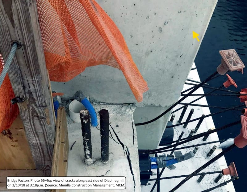
I also think the NTSB spared FIGG the coup de grâce. The NTSB puts little emphasis on the cracking that was photographed between 3:16pm & 3:18pm on March 10, 2018, 2-1/2 hrs after the transports were removed and 1 hour before the PT rods were detensioned. There was already a visible crack in member 12, longitudinal cracking in #11 and the spalling on the deck at the edge of the diaphragm was great enough to have been accompanied by cracking on the north face of the diaphragm. The bridge was most likely already damaged beyond repair. There was only one opportunity, to attempt to repair the concrete and that was while it was still on the SuperShores in the casting yard.
photo_66_kdzyyk.jpg

Emails between Figg & MCM regarding when the detensioning took place and if the photos taken between 3:16pm & 3:18pm, were before detensioning, establish that FIGG knew the new cracking had begun before detensioning.
When Louis Berger's, Dr. Shama, first modeled the complete bridge, he did so with the PT bars in #2 & #11 fully tensioned. He found the compressive forces in #2 & #11 far too high. FIGG assured Dr. Shama that #2 & #11 would be detensioned immediately after the bridge was set. It may be that the FIGG employee that Dr. Shama worked with, was one of the FIGG staff on vacation at the time of the collapse and Dr. Shama's concerns not known to others at FIGG. It seems, detensioning possibly slowed the the failure of #11 by reducing the compressive force in #11 and the decision to retension precipitated the collapse.
 
epoxybot said:
There was only one opportunity, to attempt to repair the concrete and that was while it was still on the SuperShores in the casting yard.

I would disagree that there was ever any opportunity at all to "repair" the concrete. The design itself lacked any shear steel within the concrete for connecting strut #11 to the deck. The only "repair" that could have been done would have been to introduce a massive steel tie sufficient to "capture the node" at #11/#12 and tie it back to the previous node on the deck. There was not one possible modification to the concrete that could have had any preventive effect capable of avoiding collapse.
 
I ran across this news item a bit ago, about a major bridge being built in Corpus Christi, Texas:
What I find is rather confusing. The "design" has been suspended but I found other links that seem to indicate the bridge is half-built. One article mentioned the contractor was the same one as the FSU bridge, but it's not. This article indicates Figg is designer of the new Harbor Bridge, but that's not mentioned anywhere else that I find.
 
Ooooh, look, concrete trusses! Good thing they contracted an engineering firm with a proven track record for making that work, right?

Flatiron said:
...Twin precast concrete box girders with precast delta frames provide maximum durability for the harsh coastal climate, with shapes for maximum strength and stability in extreme wind conditions...

Screen_Shot_2019-11-15_at_3.34.22_PM_ouaaqs.png
 
Re: Repairability

When a girder fails, usually the entire girder is replaced as a repair. Since this bridge was designed as a single girder, the only practical form of repair is total replacement. Since the whole idea of the single girder was to lower cost, it should therefore not have been a huge burden to scrap it in the casting yard. This bridge was treated like a red-headed stepchild.
 
How funny - that exact phrase has been running thru my mind.
That brings us back to the beginning - and the question of "Who decided to abandon the whole project?"
The collapse would have at least aroused the attention of the design team. With 30 days of study, the problems could have been identified and corrections made in the detailing while 90% of the forming would have been reused or at least reconstructed to known dimensions. Start building the back span immediately and concurrently with the casting of the replacement to the main span. Add 6 months to finish date - that would seem better than what we have now - nothing.
Or better yet design it using steel - much lighter so foundations are adequate - the size has already been approved, the location determined - just need a concentrated effort to redesign and save a project.
Had there not been loss of life this project might have been resurrected. Those taking action and closing the street would have been heroes.
If only the street had been closed immediately at the end of the March 15 meeting.
As we know now, there would not have been time to shore it and save it, and that fact would have pointed out the wisdom of closing the streets, thereby certifying the heroes.
Was there a knee jerk reaction that led to the decision to abandon this 'red headed step child'?
Professional reputations would have been stained, and the costs would have been significant, but there would have been a completed project.
I have always wondered why the back span was not constructed concurrently with the casting of the main span. I do not see anything significant that would have prohibited that.

 
Vance, consider what might have happened if they had closed the road after the March 15th meeting.

They would also have suspended the retensioning of the PT bars in 11, since putting up a crew would have been unsafe. If the PT bars had NOT been retensioned it is possible that the bridge could have held until the shoring was in place. It really depends on how quickly they could support the node in question.

What I’ve long found ironic is exactly what jrs_87 said: this was the red headed stepchild project! That exact phrase has been running through my head since the week after the collapse.

After going through everything in the docket, watching the October 22nd meeting twice and reading the final report, I can only conclude that for all that this was a special, novel project for FIU, to FIGG and MCM it was just a little pedestrian bridge. It did not get the attention it needed from the design or construction firms.

While MCM was ultimately in charge of the build site, they abdicated their oversight to the mighty FIGG EOR rather than listening to what the bridge itself was saying. Frankly, with the rush to retension the PT rods they proceeded even though the Coranado group PT inspector was not present- which should never have been allowed to happen. There was no one in the March 15th meeting who had the courage to stand up to the FIGG EOR and call BS on the plan.

This project was too small to garner FIGGs real attention. Clearly the EOR was very busy with more important projects. I am still rather stunned that the reason the peer review was abbreviated was because FIGG dropped the ball by planning to use their internal offices for the review rather than a seperate firm. Then they had to rush to get the design rubber stamped in time. I find it telling that even FIGG can not explain how they used their models to extract the original calculations for capacity and demand on the nodes. That’s how little this project meant to them, until it blew up in their faces.
 
jrs_87 (Mechanical) My bad, now I've started a chain of March 15, 2018 references. It is indeed March 10, 2018.

FortyYearsExperience (Structural) While I agree that there was never a point at which a repair could be 'effective', I can't help but mark the point in time, when an examination of the cracking should have taken place and was summarily dismissed by FIGG. I did contemplate the futility of the suggestion of a repair. Figg was given opinions/concerns regarding the node/s by FDOT-Tom Andres, BPA-(Cold Joint) & Louis Berger (Compressive Forces in PT tensioned #11), so when a problem developed in the casting yard, it should have been the wake up call.

Kestrel42 (Bioengineer) How does one shore the bridge? You cannot send workers under the bridge. Do you bring the transporters back? There were cracks in the #1/#2 node as well. The cantilever resisting PT action cannot be restored.
 
Status
Not open for further replies.
Back
Top