Eng-Tips is the largest engineering community on the Internet

Intelligent Work Forums for Engineering Professionals

Miami Pedestrian Bridge, Part XIV 78

Status
Not open for further replies.

JAE

Structural
Jun 27, 2000
15,432
0
36
US
A continuation of our discussion of this failure. Best to read the other threads first to avoid rehashing things already discussed.

Part I
thread815-436595

Part II
thread815-436699

Part III
thread815-436802

Part IV
thread815-436924

Part V
thread815-437029

Part VI
thread815-438451

Part VII
thread815-438966

Part VIII
thread815-440072

Part IX
thread815-451175

Part X
thread815-454618

Part XI
thread815-454998

Part XII
thread815-455746

Part XIII
thread815-457935


Replies continue below

Recommended for you

Earth314159 said:
In a true truss, there are zero shear forces due to PT.

Hi Earth314159. I am not sure what you are suggesting here and am curious to understand the function. Are you suggesting that in a true truss there are no shear forces to be found if post tensioning (PT) is provided? I'm not sure if PT will remove shear forces from a truss.

Thanks for your thoughts on this.

 
Hi 40 years,

No, that is not what I am suggesting. There is still shear in the structure due to gravity loads. The PT in a "true" determinant truss does not add to any of the member forces (including shear). It only adds minimally to the horizontal shear at #11 and #2 in this truss which is not determinant.

The compression in the concrete created by the tension in the PT is equal and opposite with a net zero member force.

PT in a true truss can camber or otherwise deflect the truss but the net members forces will be zero if you look at that PT case in isolation. You use the laws of superposition to add back in the other cases.
 
Hi all, I've been distracted by the wildfire and power cutoffs here in the SF north bay (everything is fine at home, except for the frayed nerves), but I just had some time to look at:
FIGG Bridge Engineers, Inc Party Submission Findings Conclusions Recommendations, and Attachments 628567
and I noted some differences between the way FIGG presents the WJE analysis and the WJE report itself.
I have two questions that are bothering me.
One: If the truss was not supposed to crack when the shoring was removed, why didn't this raise questions about how it was constructed?
Two: Pate headed down to FIU to calm people down. Would it have turned out different if he had made an effort to understand what they were upset about?

SF Charlie
Eng-Tips.com Forum Policies
 
Stay safe there - hopefully this will lead to some reasonable forest management procedures.
One - Some concrete cracking is normal and not of structural significance. I do not have the dimensions of "acceptable cracking" at my fingertips - I recall FDOT (I think - from NTSB meeting) sets 1/2" deep and either 0.002 or 0.006 inch width. That is for normal structures and there was nothing special about this one, right? (Hint - it was a truss).
I also recall an NTSB comment that on the morning of March 15 the cracking was 40 times an acceptable limit.
Two - I don't think the EOR made an engineering call on March 15.
 
Per jrs_87 links:
Unfortunately, the ENR article ends seemingly incomplete and it incorrectly states the bridge design would use cables attached to the pylon instead of faux stay pipes.

This opinion from a member of the NTSB is pretty straight-forward in stating the design error was clear yet the group think behavior overrode any dissenting response/concern.

What I still have not seen addressed officially is the issue that has been broached by many posts in this forum, regardless of all the talk/calculations on the applicability of shear capacity at the critical nodes - based on joint preparation and such, shouldn't the main span have been designed to be a fully safe and functional self-supportinhg span, not reliant on the future addition of the small back span to 'capture the 11/12 node'? Is this a common design/construction scheme - build one section of a multi-span structure with knowledge that it is reliant on another yet to be constructed section? Shouldn't individual sections stand alone unless they share beams? My naivete shows . . .
 
As in "the sheer incompetency of not recognizing a shear failure when you see one"?
Or maybe " the sheer magnitude of the consequences of the shear failure before your eyes"?
That sheer looks like a problem to me. :)


It certainly should have had the capacity to support itself and any construction loads, as well as withstood the rigors of transport, without failure and with some room to spare. And I believe this was the intent.
The concept of every piece having its final capacity at time of erection is not efficient and not required in many stages. An example is a precast girder which can support formwork for a yet to be placed concrete slab. The slab can be considered to be composite when completed and provide far more support in the final structure but the girder acting alone only needs to have the capacity to support (safely) the construction activities and the wet concrete and forming. Once cured, the intended strength is developed. If the designer does not screw up.
Not at all. You are right on point. There are calculations by the design firm that address shear in node 1/2. but I have found no calcs for node 11/12. It appears node 11/12 was not properly addressed in the design.
But I have to wonder about the long term service of the improperly treated joints. If FDOT wants them chipped and cleaned for good sealing and to prevent deterioration, these joints would not be protected as intended by FDOT. They will be wet when it rains - they are effectively in the gutter. And deterioration of reinforcing will not be visible. Perhaps this is what Berger saw when they requested guidance for treatment of the joints.


John Coil said:
Unconventional Reinforcing Bar Layout in Diagonal Members
John Coil, SENovember 1, 2019
A review of the plans show that the longitudinal reinforcement in the diagonal member were encased in #4 ties at 12 inches on center. The longitudinal bars were not located at the tie corners, however. The plans show the bars to be located 6 inches from the corners on the member. The ties were detailed to be open ties and there were no cross ties specified. Thus there was not adequate resistance to buckling of the compression steel in the diagonal members under compression i. e. diagonal member No. 11. In addition the post-tension bars in member No. 11 were located significantly outside of the kern points. If the upper bar was re-tensioned first which I suspect is the case, it would have resulted in significant tensile stress to the lower portion of the diagonal member which it appears from the photos was already cracked. By my rather simple quick analysis of the truss as a simple pin ended member truss i. e. simple static analysis for dead load was over-stressed by about 30% per ACI 318 standards. This is not enough to cause failure but it should have raised concern for the peer reviewer.

Source: Comment to this article>
Can someone please elaborate on this comment? I suspect point of comment is diminished if the bar tension changes were staggered at 50 kips. Are two balanced bars outside kern area effectively inside area? Was 50 kips small enough a limit for concentric loading? What complication is caused by positioning of dead end anchors? Did the bars in fact cause excessive tension in 11 cross-section?
 
I've gone through a fair amount of the interviews and reports and I have a few 'main' questions:

I understand that Figg had multiple models and that some predicted greater shear forces across the 11-12 joint, but they only used the "simple-span" model and the "fixed-pylon" model which predicted lower forces. It is unexplained why they did this, but I could see them thinking that these 'should' be the worst case and thus not really checking/looking into it (or just missed it). Either way the model at the time of the collapse would have been the simple span model. I also understand that they had a solids model (Lusus) and a beam element model (Larsa). They said that these correlated fairly well. My question is - why was shear demand in these models so different (lower) than the FHWA's check and even the Figg 'hand-checks' that were part of the 3/15/18 slide presentation.

Regarding the 3/15/18 presentation. It appears that Figg checks the shear strength at this node and finds that it has adequate strength. What was wrong with this hand check?

Also I didn't realize that two of the designers were on vacation immediately following the bridge move. Including the lead project engineer. Not sure that things would have been different, but interesting to note.

EIT
 
That is a possibility because of the stressing sequence at Stage 2.
There we learn that about 11% of the deck PT was first applied ( D1) and about 24% of the canopy PT was stressed ( C2) when the PT rods in member 2 and member 11 were to be stressed. There is no specification as to sequencing the tensioning between the rods.
From calcs now underway by Earth 314159 we find that full PT in the deck will cause about 1 inch camber and dead load about 1.5 inches deflection so member 11 may have been under some load but likely much less than when spanning 174 feet or when on the falsework with full PT in the deck. Stressing one rod to max before stressing the other will induce a moment but whether that causes tension depends on the total load in the member at the time. PT acting at the kern could cause sero tension in an otherwise unstressed column, and PT outside the kern can cause tension. Axial loads at that time could overcome the tension stress and the section remain in compression across its full area. Only the numbers know.
Perhaps the analysis by Earth314159 can provide some numbers to work with here. We need the compressive load in member 11 while on its falsework and with PT tendons D1 and C2 only stressed to answer this question.
Without a computer analysis I would consider that the PT force in the deck was about 960 kips and in the canopy was about 880 kips. While those forces are somewhat close to the same value the compressive force STRESS in the canopy is much greater because of its relative size being much smaller. So the effect of the early PT would be a downward camber or a lifting of the ends. That could induce tension in members 2 and 11, making it more likely that cracking did occur from stressing one PT rod located outside the kern.
Or that PT sequence may have caused some initial cracking at nodes 1/2 and 11/12.
 
After reading the ENR link posted by jrs_87: "What Florida Bridge Collapse Report Leaves Unexplained", I clicked on the author's name to see what else he may have written for ENR and then read this item by ENR co-authors Richard Korman and Scott Judy, "Did Concrete Error Doom Florida Bridge?" Link. What eventually jumped out at me was the paragraph: Under its design-build contract agreement, FIGG’s role explicitly states that it would not serve as a resident engineer but would “at appropriate intervals visit the site to determine if the construction is proceeding in accordance with the construction documents.”

When I was going through MCM's Contracts & Purchase Orders it became obvious that MCM was really only performing as the Construction Project Management firm and the actual Contractors, were all Subs. MCM was ranked 276, down from 245 in the 2015 ENR 400. So they were a big dog in construction but I was starting to get the feeling they didn't really have the chops to be doing this level of Heavy Civil Construction. It was one of the first things I looked at, when FIU made the Bid/Submittal packages available for public viewing. Link I knew MCM had people on staff that were Florida Licensed Professional Engineers, but where were they on this project? Was MCM a "General Engineering Contractor" on paper only? FDOT also doesn't give the CEI firm any engineering authority over design.

The FIU Request for Qualifications - Request for Proposals, pg 51 lists the requirements for the Design-Build Firm’s Project Manager. Link. Specifically, The Project Manager assigned by the Design-Build Firm must be proficient with the English language, and shall possess a Registered Professional Engineer License in the State of Florida and three (3) years of specific experience in construction management on limited access facilities or have a minimum of five (5) years of specific work experience providing construction management in limited access highway facilities.

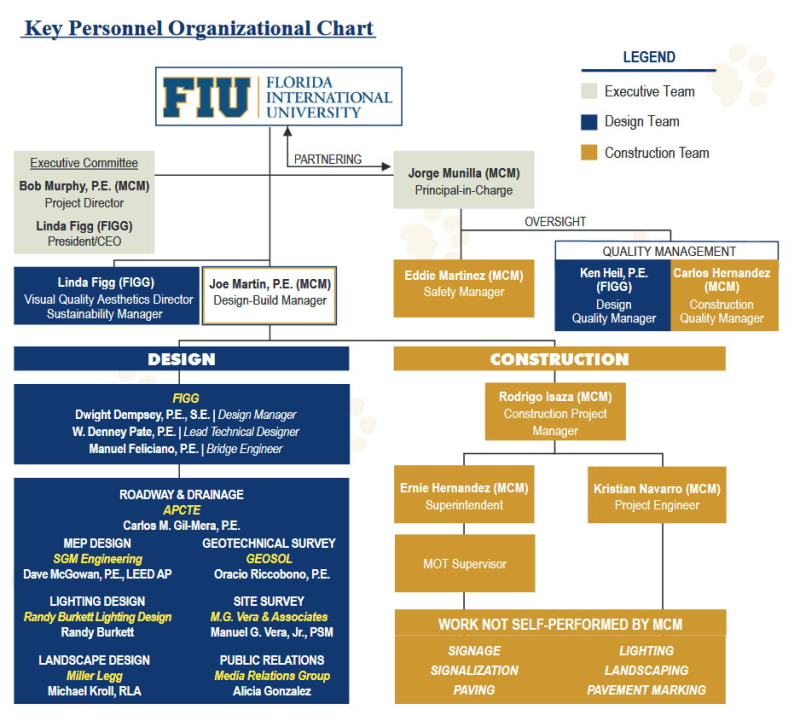
Here is the organizational chart MCM submitted with the proposal on September 30, 2015.
MCM_Org_cirpiq.jpg


The Design-Build Manager for MCM was one, Joe Martin, P.E. (LinkedIn: Link) The chart wasn't worth the paper it was printed on. Joe Martin, P.E. left MCM in October 2015 for Odebrecht. His role seems to have remained unfilled and the FIU Bridge Project put under the management of Rodrigo Isaza (LinkedIn: Link). You can see MCM's descriptions of Mr. Martin & Mr. Isaza starting on pg. 25, of their submittal. Link

It is entirely possible that Rodrigo Isaza met the minimum of five 5)years of specific work experience providing construction management in limited access highway facilities but there was a clear lack of critical understanding & thinking related to the execution of the work.

Using a 19th century nautical comparison. MCM was a big dog and as such, when they sailed into port, they anchored and waited their turn, to unload and load but when they weighed anchor and headed out to sea; they were just dog legging, direct reckoning sailors, who made the error of thinking they could blue water sail without a Celestial Navigator.
 
And yet they competed for the skyway project at an estimated $800 million and sued when they were not chosen. That project was more than 50 times larger.
This project was a reality check for all.
 
Vance Wiley - Before that project was mentioned in this forum, I was wondering just how MCM & FIGG had come together. They seem like Oil & Water as a team.
 
Oldfieldguy…

Unfortunately, this article is poorly written. For just two examples (there are others):
-- "The report went on to say that Berger knew he should have checked the math...." Louis Berger, in this case, is a company, not an individual.
-- "In other words, the contractors did crappy math." The article hits this theme quite a few times. But, it was the engineer working for the contractor who did crappy math, not the contractor.

Fred

==========
"Is it the only lesson of history that mankind is unteachable?"
--Winston S. Churchill
 
Status
Not open for further replies.
Back
Top