Continue to Site

Eng-Tips is the largest engineering community on the Internet

Intelligent Work Forums for Engineering Professionals

  • Congratulations KootK on being selected by the Eng-Tips community for having the most helpful posts in the forums last week. Way to Go!

Miami Pedestrian Bridge, Part XIV 78

Status
Not open for further replies.

JAE

Structural
Jun 27, 2000
15,460
A continuation of our discussion of this failure. Best to read the other threads first to avoid rehashing things already discussed.

Part I
thread815-436595

Part II
thread815-436699

Part III
thread815-436802

Part IV
thread815-436924

Part V
thread815-437029

Part VI
thread815-438451

Part VII
thread815-438966

Part VIII
thread815-440072

Part IX
thread815-451175

Part X
thread815-454618

Part XI
thread815-454998

Part XII
thread815-455746

Part XIII
thread815-457935


Replies continue below

Recommended for you

Tomfh said:
Everyone tries to offload as much responsibility as they can.

So true.

Figg's hired-gun (WJE) report dated Sept 18.2019, page 128 states:

capture_wje_obxhrf.png


Even though Figg's own EoR (Pate) was on site at the meeting hours before the collapse, whereby instructing the contractor and sub to continue with the stated re-stressing operation, before he traveled back to Tallahassee.

Engineers are becoming too much like f'n lawyers!
 
Anyone notice the post by
saikee119 (Structural)3 Jun 20 00:35 said:
FIGURE 31 D/C RATIOS FOR MAIN SPAN NODAL REGIONS ?
Node 1/2 has a D/C Ratio of 2.15 while Node 11/12 has a D/C Ratio of 1.62.
Would we not expect the failure to more likely have been at Node 1/2 if the cause was inadequate design capacity?
Did FHWA not consider the capacity loss due to the pipe sleeves when arriving at the D/C of 1.62??
The differences between Node 1/2 and Node 11/12 have been discussed - size of Member 2 vs Member 11, thickness of diaphragm, amount of reinforcing across the CJ, angle of Member 2 vs Member 11. In short, Node 1/2 appears to be much more robust and obviously was not expecting assistance from future construction.
But the finding was that the D/C Ratio of the failed heel joint ( Node 11/12 ) was less than that of the heel joint at the other end of the truss which did not fail.
 
Ingenuity said:
Even though Figg's own EoR (Pate) was on site at the meeting hours before the collapse, whereby instructing the contractor and sub to continue with the stated re-stressing operation, before he traveled back to Tallahassee.

Wasn’t my fault! I’d already left!
 
Rabbit12 said:
Wasn't there significant design errors made by FIGG? Where did admitting your wrong and accepting at least partial responsibility go?

Don't know about USA, but I've been told by three employers here that the insurer might walk away if you admit any fault without the insurer's prior approval.
 
Vance Wiley (Structural),

Although 1/2 was underdesigned by a bigger margin than 11/12 its members have more generous dimensions. All of then are 1'9" thick but 1 and 2 are both 3' wide whereas 11 &and 12 are 2' and 2'-10.5" wide respectively. 1/2 is type 1 and the drawings show no 4" pipe sleeves. This makes structural sense as in a bridge we always fix one end and allow the other end free to expand to avoid any thermal stress from the evironmental changes. Therefore if 11/12 were to be held down there is no need to install holding down bolts and sleeves at 1/2 end.

Having demand/capacity ratio exceeding 1.62 or higher doesn't necessarily cause an immediate failure. The bridge wasn't taking the full load at the time of collapse. Also using say a common load factor for dead load 1.4 and live load 1.6 the bridge at collapse didn't have an extra 40% dead load and the live load was zero so the structure was far from being stretched. NTSB's declaration of demand exceeding capacity is a judgement that the bridge design did not comply with the bridge design code.

As far as I know capacity reduction analysis including embedded items is never done for a footbridge in this catagory as no one would pay for knowing this information. Like many have said it is far easier to pass the problem down the line of the food chain. The designer, if he is experienced and has a conscience would probably add a note in the formwork drawing asking additional trimmer steel bars around the embedded pipe sleeves and leave the technician preparing the rebar drawing to sort out the rest. I use the word conscience because a good experienced engineer knows his bad arrangement, oversight or exclusion could kill and would try to discharge his duty with intregrity, so alerting others of a problem is the minimum one should do. A good rebar detailer, say in UK, will know the problem already and would attempt to distribute the stress around the sleeves with extra bars. After all a few steel bars cost very little but the attention to details is the quality of the engineering. I am not saying a few extra bars is what needs to save this bridge but it would surely force the rebar detailer talk to the engineer to hammer out a solution for an obviously poor arrangement.

That reminds me of FDOT Tomas Andres who marked up countless warnings on FIGG's initial design drawings about the obvious shortcomings. It was FDOT's responsibility to do peer review so he just offered his experience to a safer design.

There cannot be a better way to understand what is a good and bad rebar detailing just by comparing the condition of 1/2 with 11/12 after the collapse.
SOuth_end_not_damaged_rpbfcs.png

1/2 didnot suffer any visible structural damage when viewed from the ground. It was just moved.
Member_11-12-canopy_after_collapse_cig5fg.jpg

11/12 on the other hand had 11, 12 and deck totally separated but the separation could be consequential to the joint connection failure.
 
That quote from WJE brings shame to the engineering world. They could no more eliminate the cracks by re-tensioning than Humpty Dumpty could have been put back together by lifting him back onto the wall.
 
Ingenuity (Structural),

I am one of those who stopped reading the thread after a while when no new information came in and picked it up again so I wasn't aware of WJE's work. I wonder if it is me only having a problem to understand WJE's logic.

The cut and paste WJE's defense suggests :-
(1) WJE had accused no one monitored the cracks. This lets FIGG down.
(2) Structural/VSL own drawings mandated restressing operation to stop if existing cracks widen or new cracks observed.
(3) Evidence showed CJ was not roughened. This could cause existing cracks to widened when restressed and Structural/VSL would have several opportunities to observe.
(4) Structural/VSL could stop the operation if existing cracks widened and collapse could have been avoided.

By (1) I assume no one made any record/note of the cracks, no photo and no video. This also means nobody knew if existing cracks had narrowed or widened or any new cracks developed during the restressing. By (3) WJE now tells everybody the CJ was not roughened and the existing cracks could only widen and not close if restressed.

Since there was no crack monitoring, any restress would widen the cracks and the agreement was to halt restress if cracks widen so what was the purpose instructing VSL to restress? Was FIGG intentionally getting VSL into a trap knowing VSL was unlikely to carry out monitoring so it would not know the cracks widening and continue to destroy the bridge?

SInce there was no crack monitoring during restressing so no new crack information was available. WJE's evidence that the CJ wasn't roughened must be the same information that every contractural party had before VSL did the restressing. What was the evidence convinced FIGG/WJE that the CJ was not roughened and a restress would only widen the existing cracks? Why such information wasn't communicated to the contratual parties to stop the restressing?

LionelHutz (Electrical)

Spot on!
 
saikee119 (Structural)3 Jun 20 14:48 said:
The cut and paste WJE's defense suggests :-
(1) WJE had accused no one monitored the cracks. This lets FIGG down.
(2) Structural/VSL own drawings mandated restressing operation to stop if existing cracks widen or new cracks observed.
(3) Evidence showed CJ was not roughened. This could cause existing cracks to widened when restressed and Structural/VSL would have several opportunities to observe.
(4) Structural/VSL could stop the operation if existing cracks widened and collapse could have been avoided.


1. A supervisor was on the deck during the retensioning. Sadly he sustained brain damage during the collapse.

TheGreenLama (Structural)15 Oct 19 15:45 said:
The WJE report that you noted (p. 151, seems to be coming at the collapse from several different angles all at once. ...

This report shows they did not test the structure of the end of the deck/member-12/diaphragm


SF Charlie
Eng-Tips.com Forum Policies
 
3DDave (Aerospace)3 Jun 20 01:05 SAYS:
"No PT bars were sheared at the construction joint, at least not until the portion of the deck was cut loose for examination."

Hi 3DDave. What is the inference that we can draw from this fact?

Many thanks for your helpful input.
 
40 - if you mean that the embedded end of the bar was still in place - no kidding.

It's because you left out the qualifier - PT NUT remained in place. Sorry that you mistyped that, and depended on what you believed you had typed instead of what was actually put into words.

The bar did not remain embedded in concrete.

Here's what I think you heard in your head when typing:

"They simply ended in 'space' embedded in concrete. Thus, they the embedded ends of the PT bars moved intact, together with the concrete surrounding them."

In fact the entire upper bar remained in place and only the one end of the lower bar was embedded in concrete. The tension nut was not ever embedded.
 
Sorry if I have misled others on the lower PT rod sheared off at the CJ as I quoted off directly from OSHA Fig 63. 3DDave is correct. The lower PT rod was firmly attached to the deck during and after the collapse. The embedded anchor plate is clearly shown in OSHA Fig 64 to 70 inclusively although I only depicted Fig 63 in my earlier 2 Jun 20 01:24 post.

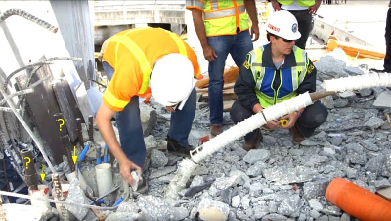
Here was the scene at the CJ showing the exposed PT rod and how it rip out from the Member 11, severed the links on it way out while the links cut the protecting plastic conduit of the PT rod. The breaking up of the lower section of Member 11, multiple cuts of the conduit and severance of the shear links were only possible if the lower PT rod was intact and firmly anchored during the collapse. Thus OSHA Fig 63 without the presence of the lower PT rod at the CJ must be the result of the post-colapse cutting by the workmen.
close_up_of_no.11_hole_fbelrq.png

Links_broken_nijibl.png

member12-11_rubble_on_deck_bjhslh.jpg

Initially I was intrigued by multiple cuts of the plastic conduit. Only after looking at how the PT rod left Member 11 could I put the two together and realised the cuts were done by the shear links.
 
3DDave (Aerospace)3 Jun 20 01:05 SAYS:
"No PT bars were sheared at the construction joint, at least not until the portion of the deck was cut loose for examination."

Hi 3DDave. What is the inference that we can draw from this fact?

Many thanks for your helpful input.
 
Steve said:
Don't know about USA, but I've been told by three employers here that the insurer might walk away if you admit any fault without the insurer's prior approval.

Yes. Same as car accidents. Your insurer carries your liability, so your mistakes are now theirs to admit to, not yours. That’s the deal.

Saikee said:
Since there was no crack monitoring

I think this is part of the general defense -Look at this shonky contractor! Not even monitoring the cracks! No wonder the bridge fell down!
 
saikee119 (Structural) 1 Jun 20 19:18 said:
According to OSHA report 11 has no structural crack at the CJ prior to the bridge removal from the casting yard.

Don't believe everything you read.

Member_11_wkttnw.jpg
 
Sym P. le (Mechanical)

A structural guy working with reinforced concrete may see cracks differently from a mechanical guy.

When an engineer declares structural cracks the remedial work will have to be structural repair able to restore the original structural integrity of the structure, Otherwise the repair is just cosmetic.

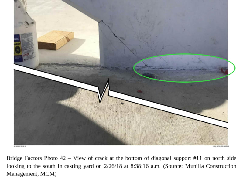
Your Fig 42 is the same as OSHA Fig 18 which came from a group of photo Fig. 17 to 20 inclusively from the OSHA report depicting the general condition around the CJ.

When the bridge bottpm was fully supported in the casting yard the application of PT rod stress in Member 11 would shortened the disgonal member slightly as both concrete and rebar have elastic modulus. The cracking in your Fig 42 is a consequence of it. At that condition the bridge structural integrity had not been compromised. That would be my view from a retired engineer who designed, accepted , rejected, modified, strengthened and repaired reinforced concrete structures. Legally say at a court of law the reciver of this bridge at that condition would not be able to reject the work but may be able to demand sealing of the cracks say using epoxy resin injection.

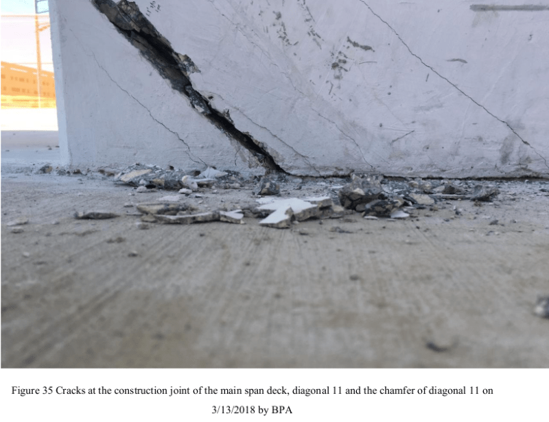
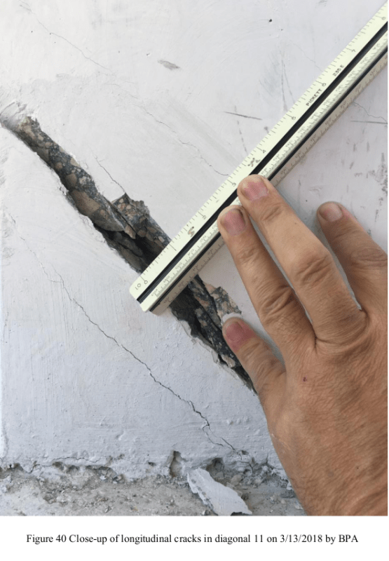
The "structural" cracks I was talking about can be seen in OSHA Fig 32 to 38 inclusively. OSHA Fig 35 is a direct comparison of your Fig 42 but after the bridge had been placed in its final position and the PT rod stresses in 11 removed. As the CJ at that time shown a complete separation and a visible 11/12 bodily displacement of about 1/2" (OSHA Fig 40) relative to the deck. At this point the bridge could be considered damaged structurally and would no longer be servieable. Additionally the 4" crack depth in the deck showed by OSHA Fig. 30 and the 7" crack depth in diagonal 11 in OSHA Fig. 39 confirmed the bridge was beyond repair and must be partially demonlished, re-constructed, modified and strengthened if it were to be serviceable again.

Any engineer who has worked with reinforced concrete for say 20 years would know the bridge was gone just looking at the OSHA photos mentioned above.
 
saikee119, thank-you for your considered response to my short post and for clarifying the perspective of the language. It is true that I have a different approach to this issue and cannot match your (and others) experience nor your responsibilities. As such I have tried to understand the dynamics of the failure free of the encumbrance of codes and calculations. Given the unusual design application and the eventual outcome, I struggle to view the initial CJ and associated cracks as the usual affair but rather an initiation of the larger failure. I can understand that the initial CJ and filet crack presentation, pre-relocation, may not have raised extraordinary concern, however the longitudinal cracks along 11, extending from the CJ, give pause.

With the benefit of hindsight and with the mindset of critical analysis to understand the failure, I do not agree that the initial CJ crack represents a shortening of member 11 or for that matter, the slab. The photo was taken after concerns were raised when loud cracking noises were heard as the shoring was removed. Again, with hindsight, the structure was already straining, unexpectedly, under its own weight. Cracks due to shortening would and did occur prior to shoring removal.
 
I disagree with saikee19 on that crack. In my opinion, the structure had failed at that point. And rather than shortening of member 11 because of applied force, the crack was due to shortening of the deck due to drying shrinkage and PT.
 
I had a look back at some of the earlier posts and this slip point was noted pretty early on.

The key issue which I can't find is any pictures of what was sticking out of the deck slab before the pour of the no 11 column. But from the picture above at 00.35 3rd June the only thing seemingly holding this joint together is that weedy looking green cage. Mention before has been made that they have no where near the amount of steel you need for the forces on member 11 and in fact it was only the PT rods which were really holding it together. Loosen them as they did and it literally fell apart and couldn't be recovered.

As soon as you got significant movement on that joint surely these bars would have sheared off?

The really criminal part for me was the action of tightening them up without really understanding what was happening / could happen.

This was the real straw which broke the bridge, but it may well have collapsed a bit later anyway.


Remember - More details = better answers
Also: If you get a response it's polite to respond to it.
 
hokie66 (Structural)

All concrete structures crack. It is a fact of life. What matters is how severe and where.

I have been interested in looking out for concrete that has received the best quality control and attention to details. Top of my list are the Charle De Gaulle airport in France and Oslo airport in Norway where bare concrete is part of the architectural features. Yet you can find cracks there. Some have been carefully patched up and some were left unattended but the amount is among the minimum you could find.

I shall explain the crack not structural in Sym P. le (Mechanical) 4 Jun 20 22:36 Fig. 42 which is depicted again below for quick reference. The bridge was still in the casting yard and after PT rod stresses applied.

MCM_Fig_42_tflzm3.png


The same crack changed in nature and severity after the bridge had been installed at its final position and on completion of the release of the PT rod stresses in Member 11.

F35_dprcnp.png


That crack width was measured suggesting the one side had separated from the other side by approximately 1/2". I ignored the >1" width at the surface as it is the crack's interior that should be of interest to us.

F40_r9yqtw.png


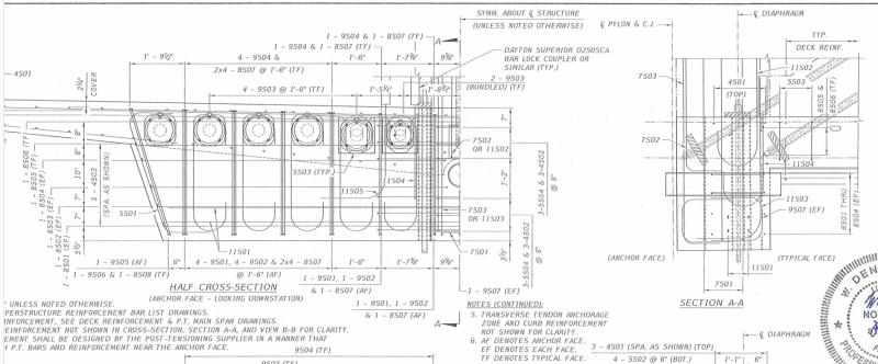
If one looks at the design drawing B47, especially Section AA, one may be able to pick up information why the same crack changed by so much.

B47_part_print_on_rear_of_upstand_elcskr.png


If PT rod tensions were applied while the bridge was in the casting yard the Member 11 would be axially compressed. The compression would also squeeze the deck axially because the PT rods anchors wanted to move from left to right. The deck was not taking load at that time.

When the bridge was placed at its final position the deck would be forced to take its design dead load and the member 11 would have one of the highest compressions in the structure. Member 11 could only develop the expected high compression if the deck provided the necessary reaction from which the deck must be stretched to develop tension to partly neutralise the previous compression from the PT rod stresses. By releasing PT rod stresses Member 11 anchores were no longer compressing the deck but wanted to deflected in the direction exactly opposite to what was before.

Thus in the MCM Fig. 42 the Member 11 was compressing the deck inward while in OSHA Fig 35 the Member 11 was stretching the deck outward. It should be obvious that the deck has a much greater scope in resisting Member 11 in compression, by buckling, than by tension of letting Member 11 to depart from the end connection. Thus the same crack in MCM Fig 42 and OSHA Fig 35 are different in nature. I for one would not lose sleep for minor concrete cracks permanently compression zone.

What stopping Member 11 moving outward and way from the end of the structure was its strcutual connection with the deck. Looking at Section AA many structural engineers would drop their jaws because there were no serious restraint availabe to prevent the whole thing from sliding out along top of the 8" drain pipe!

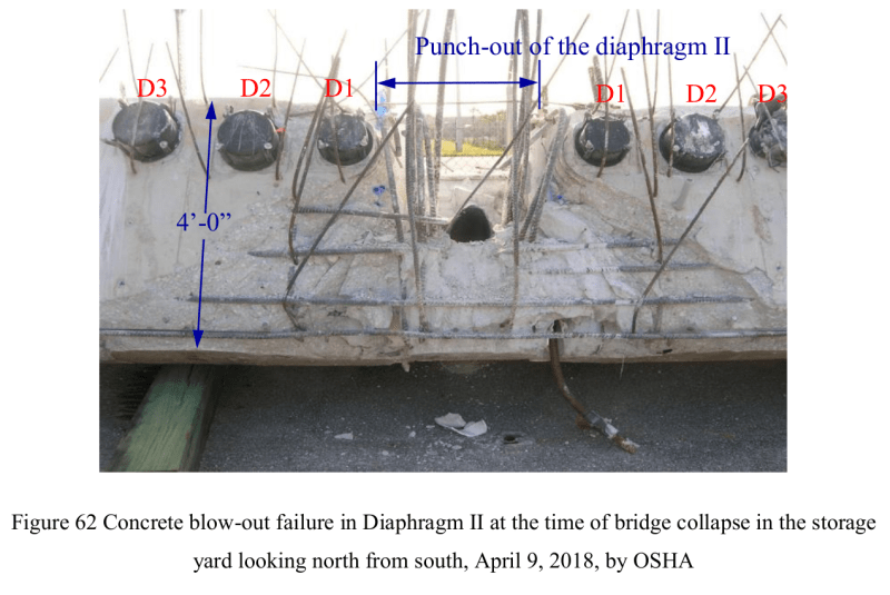
If we look at the rebar provision in drawing B47 there were some hefty 8S01, 8S02, 8S03 and 8S04 (1" diameter) at the rear of the deck but due to the physical obstruction of the 8" drain 8S03 and 8S04 were discontinued at the middle and turned 90 degree to avoid the drain pipe. OSHA Fig 62 shows all 8S01 to 8S04 inclusively intact after the failure but one side of 8S04 seems to have cast in the wrong position. The 8S01 is the lowest horizontal bar in OSHA Fig.62 below, then upward it is 8S02, 8S03 and 8S04. 8S03 was seen embedded between 8S01 and 8S02 on the right side. 8S01 to 8S04 were exposed after the surface layer of the concrete came off with 11/12. My point is had similar size horizonatal rebar were able to place above the 8" drain pipe the chance of a failure could have been significantly reduced.

F62_ndf5op.png


Design drawing B47 Section AA alone can tell us why and how the bridge failed.

In horizontal direction the only reinforcement to stop 11/12 from sliding out of the deck were just two 4S01 (1/2" diameter). One snapped at the middle and evident in OSHA Fig 63 I post previously. In the vertical direction the designer did provide a modest amout of large diameter rebar but their effectiveness was severely compromised by the presence of the 4 No. of 4" vertical sleeves and the 8" drain which destroyed bondable sections of the reinforcement. In other word even if adequate development lengths had been provided in the vertival steel some sections of the concrete were weakened, too slender and were unable to distribute the full material stress. OSHA Fig 61 to 71 inclusively confirmed none of the vertical reinforcement had failed. They were just stripped off the concrete after failure.
 
saikee,

I don't need a lecture about cracking. Have seen all too many.

But my opinion stands. The crack while still in the casting yard should have been investigated further, as it showed separation between the flange and web.

The design was fatally flawed, and hopefully will result in concrete trusses never seeing the light of day again.
 
Status
Not open for further replies.

Part and Inventory Search

Sponsor