hokie66 (Structural)
All concrete structures crack. It is a fact of life. What matters is how severe and where.
I have been interested in looking out for concrete that has received the best quality control and attention to details. Top of my list are the Charle De Gaulle airport in France and Oslo airport in Norway where bare concrete is part of the architectural features. Yet you can find cracks there. Some have been carefully patched up and some were left unattended but the amount is among the minimum you could find.
I shall explain the crack not structural in
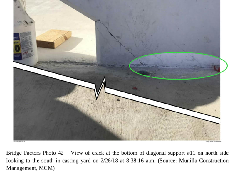
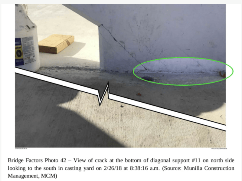
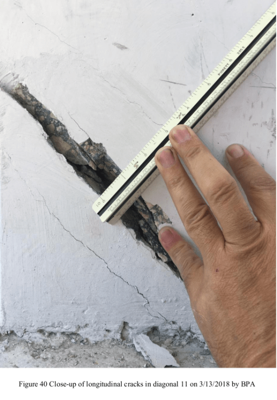
Sym P. le (Mechanical) 4 Jun 20 22:36 Fig. 42 which is depicted again below for quick reference. The bridge was still in the casting yard and after PT rod stresses applied.
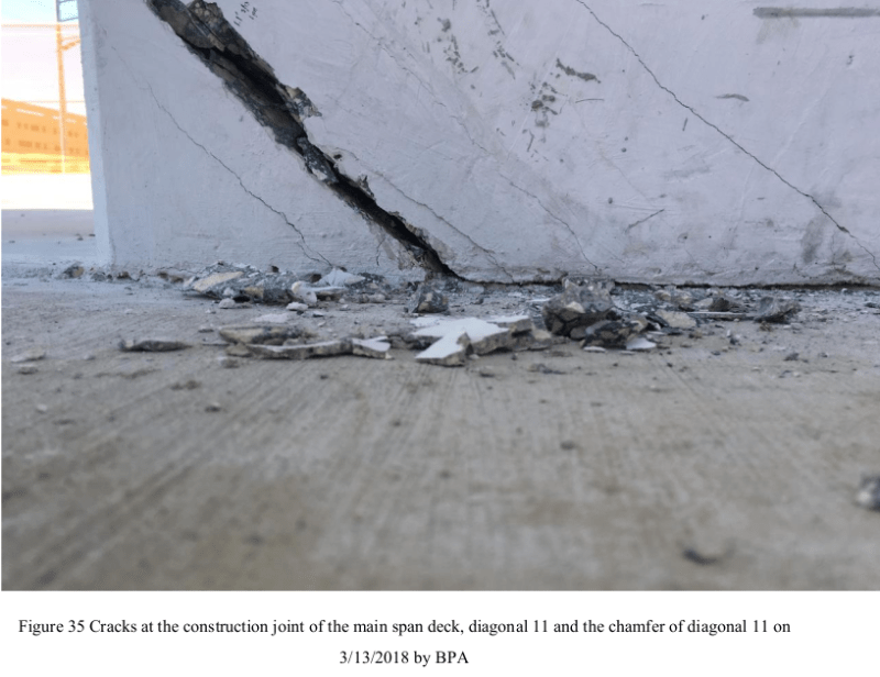
The same crack changed in nature and severity after the bridge had been installed at its final position and on completion of the release of the PT rod stresses in Member 11.
That crack width was measured suggesting the one side had separated from the other side by approximately 1/2". I ignored the >1" width at the surface as it is the crack's interior that should be of interest to us.
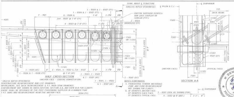
If one looks at the design drawing B47, especially Section AA, one may be able to pick up information why the same crack changed by so much.
If PT rod tensions were applied while the bridge was in the casting yard the Member 11 would be axially compressed. The compression would also squeeze the deck axially because the PT rods anchors wanted to move from left to right. The deck was not taking load at that time.
When the bridge was placed at its final position the deck would be forced to take its design dead load and the member 11 would have one of the highest compressions in the structure. Member 11 could only develop the expected high compression if the deck provided the necessary reaction from which the deck must be stretched to develop tension to partly neutralise the previous compression from the PT rod stresses. By releasing PT rod stresses Member 11 anchores were no longer compressing the deck but wanted to deflected in the direction exactly opposite to what was before.
Thus in the MCM Fig. 42 the Member 11 was compressing the deck inward while in OSHA Fig 35 the Member 11 was stretching the deck outward. It should be obvious that the deck has a much greater scope in resisting Member 11 in compression, by buckling, than by tension of letting Member 11 to depart from the end connection. Thus the same crack in MCM Fig 42 and OSHA Fig 35 are different in nature. I for one would not lose sleep for minor concrete cracks permanently compression zone.
What stopping Member 11 moving outward and way from the end of the structure was its strcutual connection with the deck. Looking at Section AA many structural engineers would drop their jaws because there were no serious restraint availabe to prevent the whole thing from sliding out along top of the 8" drain pipe!
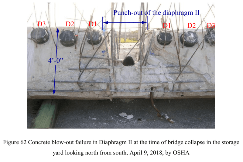
If we look at the rebar provision in drawing B47 there were some hefty 8S01, 8S02, 8S03 and 8S04 (1" diameter) at the rear of the deck but due to the physical obstruction of the 8" drain 8S03 and 8S04 were discontinued at the middle and turned 90 degree to avoid the drain pipe. OSHA Fig 62 shows all 8S01 to 8S04 inclusively intact after the failure but one side of 8S04 seems to have cast in the wrong position. The 8S01 is the lowest horizontal bar in OSHA Fig.62 below, then upward it is 8S02, 8S03 and 8S04. 8S03 was seen embedded between 8S01 and 8S02 on the right side. 8S01 to 8S04 were exposed after the surface layer of the concrete came off with 11/12. My point is had similar size horizonatal rebar were able to place
above the 8" drain pipe the chance of a failure could have been significantly reduced.
Design drawing B47 Section AA alone can tell us why and how the bridge failed.
In horizontal direction the only reinforcement to stop 11/12 from sliding out of the deck were just two 4S01 (1/2" diameter). One snapped at the middle and evident in OSHA Fig 63 I post previously. In the vertical direction the designer did provide a modest amout of large diameter rebar but their effectiveness was severely compromised by the presence of the 4 No. of 4" vertical sleeves and the 8" drain which destroyed bondable sections of the reinforcement. In other word even if adequate development lengths had been provided in the vertival steel some sections of the concrete were weakened, too slender and were unable to distribute the full material stress. OSHA Fig 61 to 71 inclusively confirmed none of the vertical reinforcement had failed. They were just stripped off the concrete after failure.