Continue to Site

Eng-Tips is the largest engineering community on the Internet

Intelligent Work Forums for Engineering Professionals

  • Congratulations cowski on being selected by the Eng-Tips community for having the most helpful posts in the forums last week. Way to Go!

Mid Span Curve In A Simply Supported Beam 1

Status
Not open for further replies.

YuleMsee

Structural
Apr 8, 2018
68
Curved_Beam_ew0iqj.png

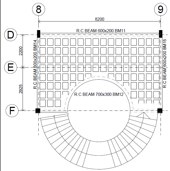
Thats the layout of first floor where the staircase terminates. I visualized this as two beams cantilevered from the columns F/8 & F/9 which then carry reactions from the curved beam, does that make sense? And if it does, how do I detail the connection at the end of the curved beam? Dimensions in mm
 
Replies continue below

Recommended for you

Is it a Waffle slab as implied?

I'd imagine the entire thing want to try span as a two way plate if it's a Waffle type configuration. Model a grillage to get an idea of how it behaving.

Can't imagine you'll get your tiny little beams to work for the torsion or deflections I'm imagining they're attracting.

Best to model it, rather than try break it down to something simple that could be hand analysed or simply visualising the load.
 
I think that your take on this is spot on: two cantilevers. I suspect that it will be a difficult design to prosecute. The curved beam support connections will need to be detailed to deliver considerable torsion into the cantilever tips unless you can justify the torque getting absorbed into the waffle slab along the length of the curved beam. I would favor the assumption of a simple load path and detailing to suit which seems to be the path that you're already on.

 
@kootk, thanks.

@Agent666, I modelled it, but for things that I don't see on a day to day basis, I like to try break them down into individual elements then try see if the two sets of results are comparable, without that I wouldn't sleep easy
 
I suspect that a fancy modelling exercise would indicate that you would need to mobilize the load path shown below. Does that path exist in some fashion? Surely. Is it going to pencil out when it comes to the detailing? Meh... that'll probably be where the rubber meets the road.

I can't resist being the pretentious ass that says this: any chance of a couple more columns? I know... I'm a trail blazer.

c01_ignylc.jpg
 
YuleMsee:
I’d provide a full width, full depth conc. beam from about grid E down to the circular opening. I would let the ribs canti. over this beam to pick up the circular opening. I would also rim the opening with a larger width conc. beam than you show. We don’t know exactly what’s happening to the left or right of your plan view, but likely assume some canti. action of the ribs and the beams on grid F from that E-W direction too. Then, some crazy rebar detailing at the rim beam of the circular opening.
 
dhengr said:
I’d provide a full width, full depth conc. beam from about grid E down to the circular opening.

I change my answer to that. It's simple and brilliant. In a way, it could represent a much improved version of the load path that I suggested, essentially moving the rear beam forward.

 
@dhengr,

brilliant, I will do exactly that, although the beam there cannot be full depth as the architect will fight back, Let me see what a 450mm deep by 600 wide beam will look.

@kootk, extra columns are a no, architect insists his entrance / lobby needs to look a particular way
 
Status
Not open for further replies.

Part and Inventory Search

Sponsor