Eng-Tips is the largest engineering community on the Internet

Intelligent Work Forums for Engineering Professionals

Minimum axial design actions on connections 1

Status
Not open for further replies.

kauri

Structural
Aug 13, 2018
36
0
0
GB
Hi, from my code NZS3404 for steel design, there is the requirement for minimum design actions acting on steel connections: "Connections at the end of tension or compression members - a force of 0.3 times the member design capacity". I'm looking at designing some epoxy bolts for small columns which primarily take gravity loads, but under uplift may experience tension. So this requirement to design the columns for 30% member tension capacity will kill my design.

Eg, I have 125SHS column sized for gravity loads and EQ lateral deflections, epoxy bolted to concrete. Under uplift it takes 20kN tension; under 30% member tensile capacity I need to size it for 400kN tension. How the f**k do I design my epoxy bolts for 400kN tension?? xD I must be missing something here.
 
Replies continue below

Recommended for you


I am not familiar with NZS3404 but i would use the elastic uplift force for the seismic or at least multiply the 20 kN with overstrength factor.. Another upper limit , the wt of foundation ( if individual spread ftg ) could be used ..

 
Hi Kauri. That is a very interesting question you ask. Most engineers would not apply this to a column. The possibly tenuous justification would be that a column is not a "tension" member. That is of course debatable because clearly under uplift it can be. But I would suggest that was not what the authors intended when they specified these minimum tension actions. (I use AS4100 which has the same clause.)

Oh and if you think the clause is rough for a 125SHS try dealing with a 310UC!

I don't think you are missing anything obvious. Just that you are taking an imperfect code too literally! :)
 
Hturkak, thanks for the ideas. In our case foundation uplift is a non-issue, with 30m screw piles! And column tension is only notable under wind loading so I won't bother with overstrength.

Thanks human, yeah I'm realizing the same idea applies to my 360UB's, haha... I would be comfortable just taking the calculated design action!

Steveh, the 30% minimum load I'm querying comes from 9.1.4
 
the 30% minimum load I'm querying comes from 9.1.4

In that case, your paraphrasing of the requirement is what is leading you to the larger requirement. Note the reference to 'minimum size of member'.

9141_y8m3jq.gif
 
Steveh, I do think 9.1.4.1 itself is ambiguous and I had taken an overly-literal interpretation. The commentary clears this up nicely, thankyou!
 
9.1.4.1 is horrible. It was the same in AS4100 in the past before being shortened. Still no clearer though, and the commentary wasn't updated so still discusses the old wording.

I believe our bridge code adopted wording that matches your original interpretation, but no one bats an eyelid at big bridge connections so not a problem.
 
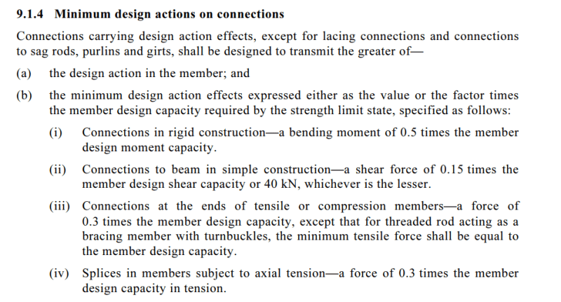
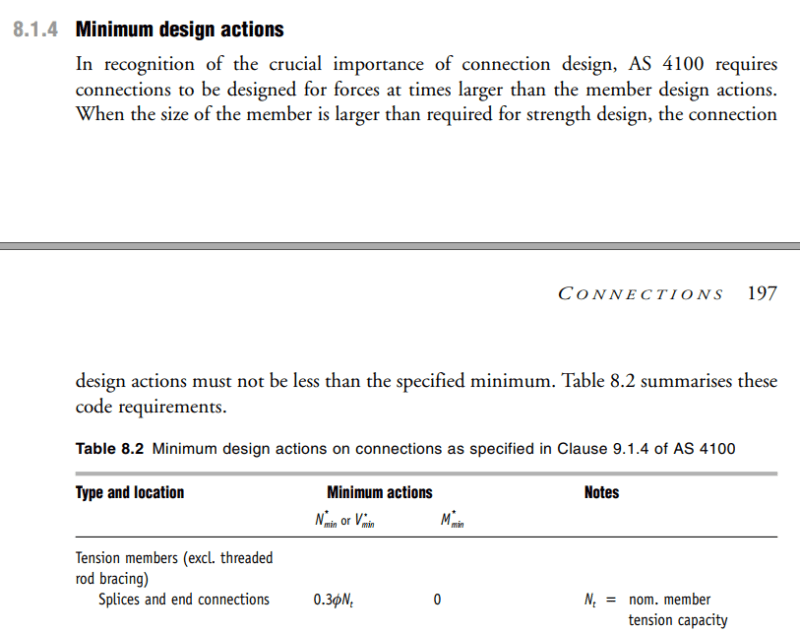
For seismic 9.1.4.1 does not applying for NZS3404 design, the heading of the clause even states this:-
image_jojpxy.png


Instead you need to be focused on chapter 12. CL12.9.2 is the one you need to look at, this clause states either design for the upper limits implied in CL12.9.1.2.2(4) or as per 12.9.2.1.1 which states CL12.9.2 is the one you need to look at, this states either design for the lesser of the upper limits implied in 12.9.1.2.2(4) or as per 12.9.2.1.1 which states 50% of the member provided (not the minimum member size like in chapter 9) provided (not the minimum member size like in chapter 9). CL12.9.2.1.2 states as well that you only need to design the connection for actions that are relevant, for example no tension, then no need to design connection for the tension minimum design actions.

The lesser bit above is key..... if you provide more info according to the questions below I can provide more guidance.

1. What EQ load have you used to come up with the 20kN load in tension? mu=1.0 Sp=1.0?
2. What category system/case number are you dealing with from table 12.2.6?
3. What category member are you dealing with for the columns (1/2/3/4?)?
4. Does this require you to have you done a capacity design, or have you been limited by any of the upper limit design actions in CL12.9.1.2.2(4)?

These connection requirements are about imparting some minimum level of robustness. But I feel your pain when you're dealing with very small loads, but the key is in the lesser requirement noted. This will mean by analysing with the right ductility and Sp factor that you can use the value straight out of the analysis

The reality is earthquakes do not follow the code, your seismic load could be two times higher than the code states, so if you just provide a design that accounts for the 20kN and no more you're potentially not really meeting the code requirements. If you're reliant on brittle modes of failure (like reliance on concrete failure mechanisms for anchors) then you wouldn't meet the general requirements of chapter 12 that requires suppression of brittle modes of failure.

[EDIT] PS - The Australians contributing are correct for any loading not including earthquake, but their advice is not strictly correct when dealing with seismic to NZS3404.

 
The possibly tenuous justification would be that a column is not a "tension" member. That is of course debatable because clearly under uplift it can be. But I would suggest that was not what the authors intended when they specified these minimum tension actions. (I use AS4100 which has the same clause.)

For seismic, if a column goes into tension, then yes you must apply these minimum robustness provisions.

Similarly, even under wind or gravity if a column goes into tension under some load cases, or has permanent tension due to the configuration, then the requirements of 9.1.4 do apply. This is the intent of the authors.

If your member does not see a type of loading, like no flexural actions, then you don't need to design the connection for flexure for example, this is the intent with respect to application of these clauses. For example, a tension only brace with nominally pinned ends, any splice would not need to also have the splice designed for 30% moment strength for example.

 
Agent666 said:
For seismic, if a column goes into tension, then yes you must apply these minimum robustness provisions.
I wasn't talking about seismic minimum robustness provisions. I was referring to the requirements under 9.1.4.1 to which I correctly summised kauri was talking about.

Agent666 said:
Similarly, even under wind or gravity if a column goes into tension under some load cases, or has permanent tension due to the configuration, then the requirements of 9.1.4 do apply. This is the intent of the authors.
Agreed. But the exact requirements of 9.1.4 are not adequately clear to the author nor myself.

That this factor applies to the "mythical minimum member size" didn't seem adequate clear to kauri and in my opinion it is even less clear in AS4100 where the wording is slightly different by the content the pretty much the same. The commentary does seem to clear up the intent, but that results in an entirely different interpretation from what I've seen some people apply.

From AS4100
AS4100_Connection_gatfjz.png


From GORENC TINYOU SYAM, Steel Designers Handbook
AS4100_Connection2_pvxfkr.png


This discussion has also been touched on here before.
 
I was referring to the requirements under 9.1.4.1 to which I correctly summised kauri was talking about

Well Kauri did say EQ forces were involved in his original post, but was inferring incorrectly the 30% requirement that only applies for non EQ loading. For seismic it is 50% of the section capacity for tension (but I await their response to my questions to clarify that this almost never applies for small loads depending on what you are trying to design and for what level of ductility as the minimum size issue is not part of the seismic route).
Kauri said:
I have 125SHS column sized for gravity loads and EQ lateral deflections

What's not to understand here.... this is how codes are written, don't know exactly how to address a certain issue... make it as vague as possible and let the industry sort it out [ponder].... [banghead]
....

The way I treat this is to take all the design actions, say M*=30kNm, N*=40kN tension (from wind case, no seismic) and N*=200kN compression. Say under the size of member actually provided my design/capacity ratio was 0.5 for tension/moment case with a 200UC46. Thats the member I've provided. But I could have gotten away with a 150UC37 with a ratio of 0.83 for the tension case (tension load case assessed in isolation), then the minimum tension connection requirement would be 30% of the tension capacity of the minimum size required for tension, being a 150UC37. For the compression/moment case I'd have a ratio of 0.94, and going down a size would not work, therefore I'm stuck with a compression splice design needing to consider 30% of the section compression capacity for a 200UC46. The is the direct interpretation of the commentary clause text: -
image_wtdoxj.png


The issue is I can also interpret it in ways that mean I never have to ever take account of these provisions. Consider the shear one for example being 15% of the shear capacity. If you have a nominally pinned web plate type connection only carrying shear, then the min size member required is one that just supports V* right, a welded section if you like with the exact web size required! So V* will be greater than 15% of the shear capacity of that minimum size member. So what was the point of the clause again with respect to the minimum size member requirement again??[banghead]

So basically I agree it is not worded very well, but the commentary expresses the intent, and if you don't believe that then that's what engineering judgement is for I guess. A code is the minimum standard, you can apply it in a logical and/or conservative way if you like, or do your own thing if you're following best practice.

 
Actually, just picked up in AS4100 that they refer to the member design capacity (it was amended in Amendment #1), not the minimum size member carry on that is still in NZS3404.

So I guess for the Aussies you don't have to worry about this. It also goes some way to explaining the intent, that these minimum percentages should be applied to the design capacity, end of story?
image_m94nhe.png


I don't think the AS4100 change is any clearer, and perhaps not even any different to the NZ (old AS) wording. Given the diversity of opinion, it's quite hard to say what either clause really means. I wanted to submit a comment on this when the code was revised, but unfortunately the first I heard of the revision was someone telling me I should use the new code.

Agent posted the AS wording in his last post and highlighted "member design capacity", but the wording is actually "member design capacity required by the strength limit state". Not really much different to the minimum member business. The member capacity required by the strength limit state is S*, but it doesn't explain how to use this in the context of combined actions, or what the member is (eg columns where one stick extends over several storeys).


The commentary infers it is percentage * phi * R_u, member design capacity is the section capacity. Where ever it refers to this in the standard it is the full capacity of the section.

I have had this confirmed by one of the authors of NZS3404 in the past for another similar clause using a similar wording/phrasing (CL12.9.1.2.2(4)(c) which refers to "design capacity of the primary member". In this context it is the full section capacity, i.e. for compression phiNs, for tension phiNt, for flexure phiMs, etc. The intent is it is the full capacity of the section, you can try swing it any way you like but this is the intent and the commentary states why (to achieve sufficient robustness).

 
But the nominal capacity =

Screenshot_20210828-174706_Box_ptlpun.jpg


And the Gorenc textbook uses the member capacity notation:

Screenshot_20210828-172044_Box_dcx8dv.jpg


If the code authors meant section capacity, they've gotten the code badly wrong.
 
The unfortunate thing is that make zero sense.

For example say you have a column with 20kN load in tension and compression and a 300kN compression member capacity and a 3000kN section tension capacity.

Then for tension using that logic you're designing for 30% of the section tension capacity (1000kN). But for compression you're designing for 30% of a potentially much smaller compression member buckling load (100kN). That makes no sense at all.

 
The commentary basically says not to go nuts with column tension splices.

Edit: Pondering more, it is conceivable that connexion academix who live in the 1m^3 box around member intersections wouldn't be aware of the distinction between section and member capacity definitions in the code, and so not take care in their wording. The members apply load to the connection but are otherwise an irrelevance.
 
Status
Not open for further replies.
Back
Top