Continue to Site

Eng-Tips is the largest engineering community on the Internet

Intelligent Work Forums for Engineering Professionals

  • Congratulations KootK on being selected by the Eng-Tips community for having the most helpful posts in the forums last week. Way to Go!

Modal Analysis - Effective Mass

Status
Not open for further replies.

TooStressed

Mechanical
Jan 28, 2022
7
Hello,

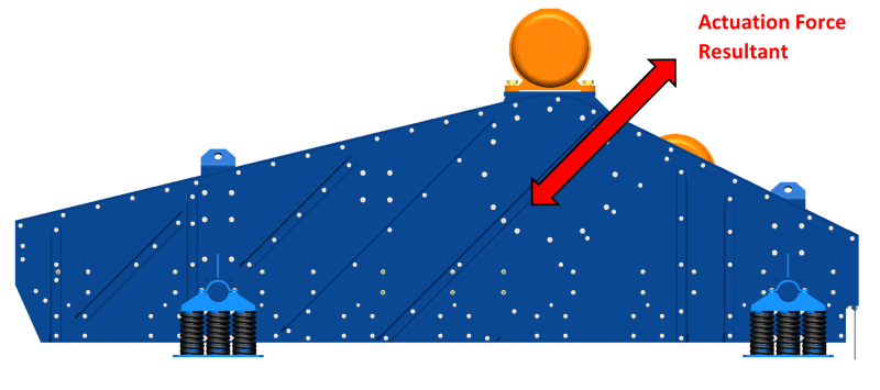
I am analyzing a material screening machine. It consists of a structure that is supported by springs. The assembly includes two motors with unbalanced masses that produce an excitation force which causes the structure to vibrate.
The motors operate at 1200 RPM (20 Hz).
As the structure is supported by springs, rigid body modes are present in the modal analysis and in reality. As expected, the effective mass fraction for each of the rigid body modes is near 1.0, with the rest of the modes having an extremely low effective mass fraction.
The modal analysis indicates modes at (or near) 40 Hz, 60 Hz, 80 Hz, 100 Hz. As these are multiples of the operating frequency, I am concerned. I'm sure that if I extract more modes I'll find many more multiples of the operating frequency. But how many modes are significant when the effective mass is dominated by the rigid body modes?
Should I artificially constrain the model? That will change the natural frequencies. How do I deal with that?
I am also concerned that while only a very small fraction of the total mass participates in a particular mode, it may be due to small component vibrating violently and increasing the stresses in the welds that attach it to the structure assembly.
I also ran a quasi-static simulation with inertia relief and identified the regions of high stress.
How can I determine if the operating frequency will result in an intolerable increase in stress values?

Thank you.
 
Replies continue below

Recommended for you

Typically a rotating impacty system will produce a lot more energy at the odd integer harmonics than the evens.

So what frequency are the RBMs?


Cheers

Greg Locock


New here? Try reading these, they might help FAQ731-376
 
The machine is not rotating. It is vibrating up and down at an angle. See the image below.
I used CBUSH elements to represent the springs. The CBUSH elements have a spring constant in their longitudinal direction only (so only a spring constant is present only in the vertical direction).
Since the structure is essentially unconstrained in the horizontal directions (into and out of the page, and left and right, in the image below), the rigid body modes in those directions are at near-zero frequencies.
The rigid body modes in the vertical direction (bouncing and rocking up and down) are at 3.3 Hz, 4.3 Hz, and 4.7 Hz. Each one of those modes has an effective mode fraction of 0.9-1.0.
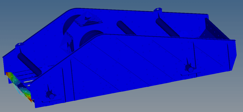
I am concerned with flexible modes that could include a component that makes up a small fraction of the mass of the structure, but might resonate and create large stresses in the welded connections that attach the component to the assembly. See the second image for an example of a mode at 60 Hz.

Picture1_iegpkw.png


modal_60_vlmpdw.png
 
As I understand the this is like material handling sieve/shaker to sort components into small and large or whatever its purpose is. The vibrations are means to shake the structure to achieve this purpose. So Vibrations are intended.
I think the design goal for such structure is to avoid failure for given period say no of years of its design life without fatigue due to vibrations. Besides fatigue, the structure should withstand high excitation without stresses going beyond yield so the structure will remain elastic in response and high cycle fatigue evaluation applies.

Since vibrations are intended, you need to consider the frequency range in which the the motor operates and those particular modes and frequencies of structure which match the natural frequencies of structure. E.g. Motor will start from 0Hz to 20Hz so the frequencies of structure in range 0-20Hz are most probably give more excitation than 2X(40Hz), 3X(60Hz) or XX modes. Normally it good to take all frequencies and modes within operating range.

So check for 0-20Hz range frequency and modes. Next thing is to consider the modes which are important with respect to the direction of excitation. The model is constrained only in vertical direction with springs attached. So I think response will be controlled in vertical direction. The other modes needs to be carefully checked in the operating range of motor and these are probably rigid modes due to no constraint in these directions. But mostly the excitation force for shaker machines is only in one direction (Vertical in your case) and hence those modes are more important than any other modes and will give higher stresses.

I think you need to perform frequency response analysis for the operating range once to check which is important mode and frequency "stress" wise.
 
Which software do you use for this analysis ? Some FEA codes offer vibration fatigue analyses based on either harmonic or random vibration studies. In this case you could use the former to evaluate failure of the screening machine after many cycles of operation.
 
@NRP99 This is indeed a shaker and vibrations are indeed intended. The goal is indeed to have the device operate for a set number of years without failing.
My process is to extract the peak stresses per cycle and then calculate the expected life based on the number of cycles that the material can handle at the given stress range. However, the weakest links in the structure are the welds. They are the most likely to fail due to vibration, and they do (either the weld itself fails or the parent material very close to the weld). Since these machines operate continuously and the stresses cycle 20 times per second, they reach millions of cycles in a relatively short period of time. Therefore, I specify that the peak stresses in the welds stay below the theoretical limit for "infinite" life.
My issue is with understanding what happens to the stresses if the operating frequency coincides with some resonant frequencies.
I'll run a quasi-static simulation with the excitation force at it's peak in one direction, and another simulation with the peak force in the opposite direction. The peak stresses (for each region of interest) will form the stress range. For welds, I need this to be in the "infinite" life range.
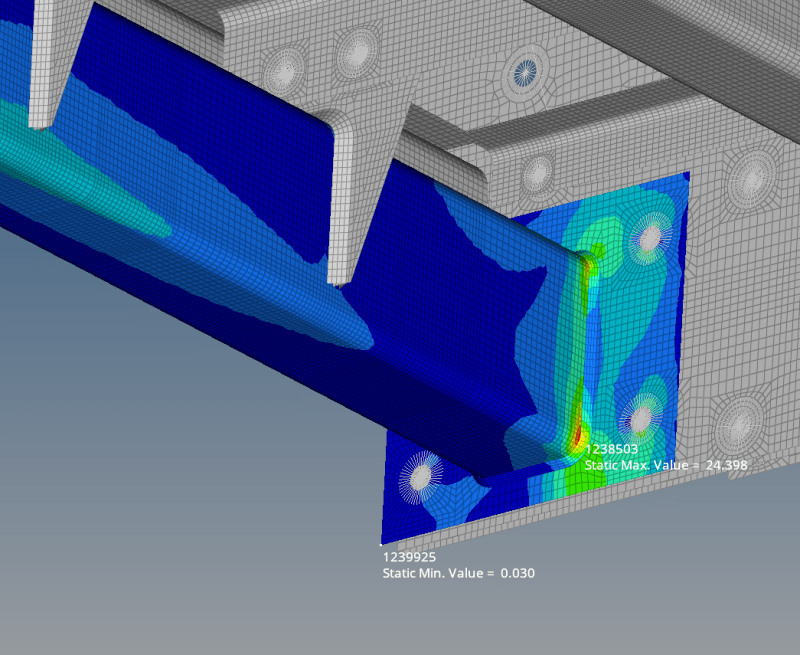
For example, the quasi-static analysis shows me that the stress crossbeam weld is 24 MPa. That's fine. But the modal analysis tells me that there are modes at 40 Hz, 60 Hz, 80 Hz, etc. So by operating at 20 Hz, the system is exciting these modes. Like pushing a swing every second, third, fourth cycle.
I don't know how to simulate/calculate/extrapolate what will happen to the stresses in that case. What happens to the stresses if the machine operates exactly at a resonant frequency?
Do I need to run a frequency response analysis? How many modes? The rigid body modes take up 100% of the effective mass.

beam_c4jtir.png


@FEA_way I'm using Altair Hyperworks. There is a package called HyperLife for fatigue analysis. I started looking into it and it's useful for extracting the stresses and calculating the life of the part but that's not my problem. My problem is determining how the natural frequencies that are multiples of the operating frequency affect the quasi-static stress results.
 
TooStressed said:
My issue is with understanding what happens to the stresses if the operating frequency coincides with some resonant frequencies.....What happens to the stresses if the machine operates exactly at a resonant frequency?
As expected, the stresses will get magnified at resonant frequencies. But by how much is the question you need to answer by conducting frequency response analysis exercise.

How much frequency range is now question since you are seeing modes at 2X, 3X and 4X frequencies. If rigid modes are with frequencies in your operating range then you need to consider it otherwise rigid modes with 0 frequencies are just fictitious modes with respect to checking the dynamic response of structure. Rigid modes with zero frequencies are checked for the purpose of whether the model is integral and whether some part is flying off. Its expected that in modal analysis first 6 modes to be rigid body modes with 0 frequency.

What is the motor drive frequency range? Its better you check the response of your structure by varying frequency range which you think is important in frequency response analysis. In frequency response analysis, you may subject shaker structure to the excitation forces at frequency range of say 0-80Hz and see the response of structure in terms of stress at peak frequencies.


"As expected, the stresses will get magnified at resonant frequencies. But by how much is the question you need to answer by conducting frequency response analysis exercise."

Bit tricky if you don't know the damping of each mode. How much damping does the material on the shaker table add?

Cheers

Greg Locock


New here? Try reading these, they might help FAQ731-376
 
Yes. Normal material damping, springs attached to structure as well as any hydraulic system attached for excitation purpose will make the modes damped and response of the structure will be slow like damped system which is useful for design life, I guess. The stresses will still magnified but the magnitudes will be less than undamped system.

GregLocock said:
Bit tricky if you don't know the damping of each mode. How much damping does the material on the shaker table add?

Material to be handled on shaker table will add to mass of total system and will decrease the overall system frequency. Is it going to add any damping in the system, I guess negligible. Is it what you meant?
 
Well, loose materials are a tried and trusted way of damping steel structures (sand or lead pellets wotk well). So no, I don't agree.

Cheers

Greg Locock


New here? Try reading these, they might help FAQ731-376
 
And ignoring structural damping for fatigue loads will render the results meaningless except as a lower bound for life.


Cheers

Greg Locock


New here? Try reading these, they might help FAQ731-376
 
GregLocock said:
Well, loose materials are a tried and trusted way of damping steel structures (sand or lead pellets wotk well). So no, I don't agree.

And ignoring structural damping for fatigue loads will render the results meaningless except as a lower bound for life.

I agree damping should not be ignored. But how the material to be handled add to damping besides mass to overall system? Are you pointing towards the inherent material damping of material to be handled? What's lower bound life? Is it life increase due to less stress range?

Oh no, I missed the points completely. Could you please explain?
 
I don't have experience with frequency response analysis. What will it show me? The amplification factors that I can multiply the quasi-static stress results by to estimate the dynamic/resonant stresses?
The material being vibrated varies. Sometimes it's a pile of rocks, where the big rocks keep bouncing to the discharge end of the shaker and the little rocks fall down into a collection bin/conveyor. Other times it's sand that gets washed as it bounces to the discharge end. The material undoubtedly adds dampening and increases the stresses. When I simulate a loaded screen I include distributed masses on the flat bed for the quasi-static analysis where the excitation force is directed up, and no masses when the force is directed down, because the material is loose and not fixed to the structure. I'm open to other ways of doing it, if anyone has suggestions.
I don't know what the internal dampening of the structure is. I don't know what a reasonable estimate would be, or how to include it in my simulation. Surely excluding internal dampening is a conservative simplification that will provide a "worst case" result. No?
So my question remains: If the quasi-static analysis showed a stress of X at a specific location, and the modal analysis showed modes at 40/60/80/100/etc Hz, by how much is stress X amplified when I operate at 20 Hz? And how many of the modes do I need to consider to ensure that I don't miss a relatively small portion of the structure resonating and cracking its welds?

Thanks.
 
" But how the material to be handled add to damping besides mass to overall system? Are you pointing towards the inherent material damping of material to be handled? What's lower bound life? Is it life increase due to less stress range?"

Um, can I guess you have never encountered a system like this?

Damping (and friction) extracts energy from the system and turns it into heat. Small particles rub together as they bounce around and turn kinetic energy into heat.

Lower bound on life is because by ignoring damping you'll get huge predicted stresses at resonance and so will massively overpredict the damage to the system in one cycle.

I'd have thought all of this was entirely obvious, to be honest.


Cheers

Greg Locock


New here? Try reading these, they might help FAQ731-376
 
by ignoring damping you'll get huge predicted stresses at resonance and so will massively overpredict the damage to the system in one cycle.
I need help predicting stresses at resonance. Once I get a handle on that, I'll worry about downgrading the stresses due to dampening.
 
Hi

In theory, if you ignore damping, the stresses will by huge (infinite).

Run a harmonic response analyses and include the entire working frequency range. Also include the natural frequecies in the analysis and you should get som info on what is happening. If you plot results vs frequency you should see high peaks for the natural frequencies.

Thomas
 
GregLocock said:
Um, can I guess you have never encountered a system like this?
Damping (and friction) extracts energy from the system and turns it into heat. Small particles rub together as they bounce around and turn kinetic energy into heat.
Lower bound on life is because by ignoring damping you'll get huge predicted stresses at resonance and so will massively overpredict the damage to the system in one cycle.
I'd have thought all of this was entirely obvious, to be honest.

Yes. I have never analyzed shaker system and encountered till today. I mostly do statics (90% of time) and the response above is based on what I know/learned about dynamics and whatever experience in dynamic analyses I do. But these are very simple problems like impact, drop etc. And to be honest, it was not obvious to me/was unaware that friction(damping) of material to be handled with shaker surface will consume lot of energy given by shaker and hence needs to be taken in to account in form of Coulomb damping. Thanks for explanation.
This is new learning to me. But I did know and is obvious that damped system response is low and the stress (and system response) magnitudes will be lower than undamped system at resonance.

@TooStressed
I suggest to get the know-how and theory of frequency response/harmonic response and random response analysis. I assume you use Radioss/Optistruct solver then start with simple problem like here. Search help documentation for both theory and example problems. After sufficient understanding is achieved, run your model without including damping first and then including damping.
For structural steel material damping, frictional Coulomb damping or system based damping values , I think you need to find out yourself for shaker application. Try searching in past reports or past experimental data if its available or search for published papers online/offline. You can also search help documentation for starter values in example problems.
 
@NRP99 Thanks. I'm using Optistruct and obviously need to spend some time learning how to run dynamic simulations.
 
TooStressed said:
I used CBUSH elements to represent the springs. The CBUSH elements have a spring constant in their longitudinal direction only (so only a spring constant is present only in the vertical direction).

Do the springs really have stiffness solely in the vertical direction? Maybe this is a dumb question but shouldn't they at least some stiffness in the other directions? Perhaps this is why some of your modes are low.
 
TG_eng said:
Do the springs really have stiffness solely in the vertical direction? Maybe this is a dumb question but shouldn't they at least some stiffness in the other directions? Perhaps this is why some of your modes are low.
The springs do not have stiffness solely in the vertical direction. Rigid body modes are always close to zero if there is no stiffness. By including stiffness in the vertical direction, rigid body modes in the vertical direction increased from zero to around 4 Hz. If I include spring stiffness in the lateral directions, the other rigid body modes will increase to around 4 Hz too (or whatever is correct for the stiffness value I include in those directions).
In any case, low rigid body modes are not my problem. Stress magnification factors at higher order flexible modes are.
 
Status
Not open for further replies.

Part and Inventory Search

Sponsor