Continue to Site

Eng-Tips is the largest engineering community on the Internet

Intelligent Work Forums for Engineering Professionals

  • Congratulations waross on being selected by the Eng-Tips community for having the most helpful posts in the forums last week. Way to Go!

Modeling Bolts in Shear

Status
Not open for further replies.

tlewis3348

Mechanical
Aug 23, 2017
31
The attached file contains a project with two simulations. The first models a bolt uses frictional contact exclusively to restrain its motion. The second uses the same geometry and replaces the contact that would be between the shaft of the bolt and the clearance hole with a revolute joint. The difference in the two simulations is significant. The first captures the fact that the two plates are going to slide with respect to each other and eventually begin applying a shearing load to the shaft of the bolt. The second does not capture this behavior and makes it seem that the two plates will not slide with respect to each other.

My question is whether this is an inescapable result of the nature of a revolute joint, or if there is a way to capture the sliding behavior of the two plates with a revolute joint. Furthermore, if the applied load is more than 3702 lbs (which is what I have it set at currently), the plates come into contact with the bolt, the simulation takes far longer, and warnings and errors are thrown when it does finally finish.

In a small and simple simulation like this, it isn't that big of a deal, but in a larger simulation, these issues can make the model run for much longer than I have time to let it run. Furthermore, when the simulation does finally finish, it will often tell me that it didn't converge and the results can't be trusted. Is there a better way to model a bolt like this that is at risk of being sheared off?
 
 http://files.engineering.com/getfile.aspx?folder=6f770a75-f0c1-46fc-a4de-528a802677fb&file=Bolt_Shear.zip
Replies continue below

Recommended for you

Could radial gap joint be used to capture the relative sliding of the plates?


Edit: apparently radial gap joint is supported only by rigid dynamics solver.

In my opinion the first model using frictional contacts is a correct way to model
a bolted connection. I would expect the convergence to be slow if there is a lot
of sliding between the surfaces.
 
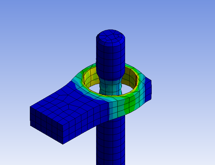
Well, when I use frictional contacts exclusively in a larger model, I end up getting very strange non-physical behavior. For example, in some cases, a bolt gets flattened down to the thickness of a piece of paper or less which results in its volume being spread out over an enormous area. In other cases, a pin going through a hole of the same size produces such an incredible force between the two surfaces that the two surfaces are pushed away from each other like they are made out of soft foam and are repelling each other magnetically. To say the least, the behavior is not anything close to realistic when I just use frictional contact. This is extremely unfortunate, because one of the things we wanted to know from this simulation is whether the bolts we were using were going to be sufficient to hold two plates together, or if the mass on one of the plates would end up shearing the bolts off. It appears that the best we can do at this point is to either have localized non-physical results (using joints to create a bolt that is guaranteed not to shear off), or have globally non-physical results (using frictional contact that results in bolts and other components somehow being completely destroyed in non-physical manners).
 
If you want to share a model which seems not to be working, I would gladly take a look. Lately I have been modelling bolted connections quite a lot, here
is one example of stresses in bolt after pretensioning (no external loading yet). In this model both the bolt head and nut are connected to plates
using bonded contacts. Between plates are frictional contacts. I have not modelled contact between shaft and plates.

(scale used in this picture is about 200, this is why it seems that surfaces are penetrating quite a bit)
 
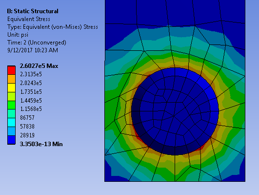
I don't think I can share the model since its proprietary information. I can share the screenshot below showing the behavior I'm seeing. I don't currently have results showing the behavior with the bolts, but I'll try to generate some of those as soon as possible.

Capture_l8qkpk.png


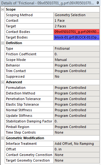
Any idea what might be causing this to happen? Here's the settings for the contact connection there:

Capture_gdtvwx.png


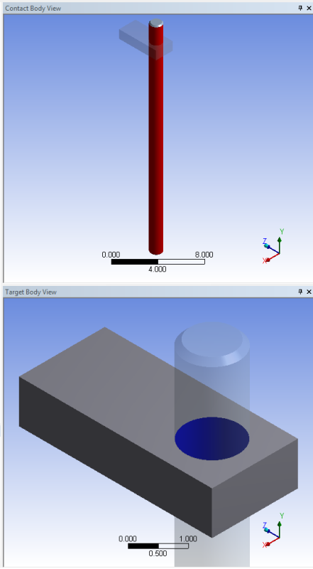
And here's the surfaces in contact:

Capture_kkholx.png


I'm not sure whether that's enough information for you to be able to help at all, but any you might be able to provide would be greatly appreciated. At this point, I'm at a complete loss for where to look for problems. It's not at all clear to me how ANSYS could end up generating these results.

Edit: All materials are generic structural steel.
 
Hi tlewis3348,

There was no numerical scale on your plot. Was the displacement small?

I'm not sure if this replicates your setup. (Note that Ansys Auto Scale is at 6400x magnification below, making it look weird):
ha6in2D.png


The original geometry was a simple cylinder in block with no interference but the hole diameter is the same as the cylinder diameter (10mm):
X0mVrsm.png


The reason, as I understand, is because the mesh is not exactly coincident. From the end view, the mesh has tiny interference:
aqlJWFv.png


Once the mesh is lined up properly, the interference is negligible:
pgf1snF.png
nALo9f0.png


Best regards,
Jason
 
As far as how much magnification was in the image I showed above, I ran that simulation quickly just to get a screenshot of the behavior I've seen above. Therefore, I didn't let the simulation run for very long, and just magnified the results to be similar to what I'd seen before. Whatever the case, the magnitude of the effect depends on how long I let it run. If I let it run for a while, the effect can be quite significant at 1X scale. Anyhow, I will try aligning the mesh and see what happens. Thanks!
 
So I just did the simulation with the mesh aligned, but it is still producing the bad results:

Capture_qxttbl.png


This is at 1X scale. Note that these results are not converged because the simulation crashes before it will finish. Ultimately, the only way I've found to get the simulation to run without crashing is to use joints to represent these interfaces rather than frictional contact. This problem is though that apparently joints are only valid if you can accurately assume that the joint won't fail in reality.
 
What load steps boundary condition are you using? What was the error message?

OP said:
Ultimately, the only way I've found to get the simulation to run without crashing is to use joints to represent these interfaces rather than frictional contact. This problem is though that apparently joints are only valid if you can accurately assume that the joint won't fail in reality.

With a little more effort, I'm sure you can get your frictional interface to work. Here's a recorded webinar by Simutech.

There are different trade-offs to using joints instead of friction interface. If you must have preload, slip etc, frictional interface is the way to go. I have seen people extract forces from simpler bolt model representation (e.g. contacts, beam element). Those forces are then plugged into a spreadsheet. If it's a concern, a more detailed frictional interface model is created.


Kind regards,
Jason
 
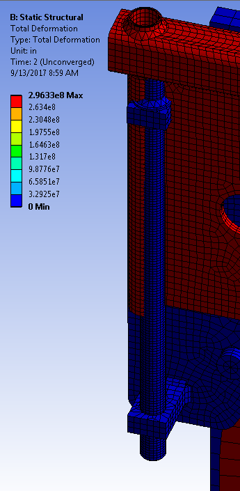
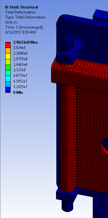
So between the blog shared by @L_K and the tutorial on contact in ANSYS here: I changed the contact detection method to "Nodal-Normal To Target" and the normal stiffness factor to 0.2, and also changed the pinball region on some of my contact sets to be non-zero. However, even though I did that, I'm still getting incorrect results. Compare the deformed on the left (scaled to 2e-8 X) and undeformed on the right results shown below:

Capture_phwcuy.png
Capture2_gmgvgg.png


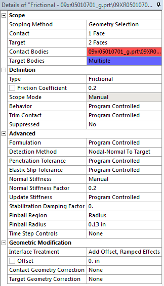
Clearly, whatever settings I have for contact between these two parts is not effective at enforcing contact between them. These are the settings I'm using:

Capture3_f0fgmz.png


Note that the diameter of the pin is 0.25in smaller than the diameter of the sleeve, which is why I set the radius of the pinball region to 0.13in.

Any suggestions as to what settings I have wrong would be greatly appreciated. I feel like I'm shooting in the dark here.
 

What was the error message?
How does the force convergence plot look like?
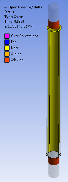
Does your Contact Tool>Status plot show the friction contact as "Far"?


Kind regards,
Jason
 
These are the errors/warnings I'm getting.

Code:
Error	An internal solution magnitude limit was exceeded. (Node Number 178117, Body CT51EA480_G21(Open 0 deg w/ Bolts), DOF UY) Please check your Environment for inappropriate load values or insufficient supports.  You may select the offending object and/or geometry via RMB on this warning in the Messages window.  Please see the Troubleshooting section of the Help System for more information.	Project>Model>Static Structural>Solution	Wednesday, September 13, 2017 10:13:15 AMError
Warning	The solution failed to solve completely at all time points. Restart points are available to continue the analysis. 	Project>Model>Static Structural>Solution	Wednesday, September 13, 2017 10:13:15 AMError
Warning	At least one body has been found to have only 1 element in at least 2 directions along with reduced integration.  This situation can lead to invalid results or solver pivot errors.  Consider changing to full integration element control or meshing with more elements.  Offending bodies can be identified by Right-clicking in the Geometry window and choose Go To -> Bodies With One Element Through the Thickness.  Refer to Troubleshooting in the Help System for more details.	Project>Model>Static Structural>Solution	Wednesday, September 13, 2017 10:13:15 AMError
Warning	The unconverged solution (identified as Substep 999999) is output for analysis debug purposes. Results at this time should not be used for any other purpose.	Project>Model>Static Structural>Solution	Wednesday, September 13, 2017 10:13:15 AMError
Warning	Although the solution failed to solve completely at all time points, partial results at some points have been able to be solved.  Refer to Troubleshooting in the Help System for more details.	Project>Model>Static Structural>Solution	Wednesday, September 13, 2017 10:13:15 AMError
Warning	Solver pivot warnings or errors have been encountered during the solution.  This is usually a result of an ill conditioned matrix possibly due to unreasonable material properties, an under constrained model, or contact related issues.  Check results carefully.	Project>Model>Static Structural>Solution	Wednesday, September 13, 2017 10:11:00 AMError
Warning	Contact detection on All Bodies is detected during the model assembly process. During model assembly process, contacts are detected between assemblies, for each assembly, and may also be imported from upstream system(s). Please verify that duplicate contacts have not been generated through contact detection on All Bodies, and suppress/delete any duplicate contacts.	Project>Model>Connections>Contacts	Tuesday, September 12, 2017 2:05:03 PM

Here's the force convergence:

Capture_kpl1kx.png


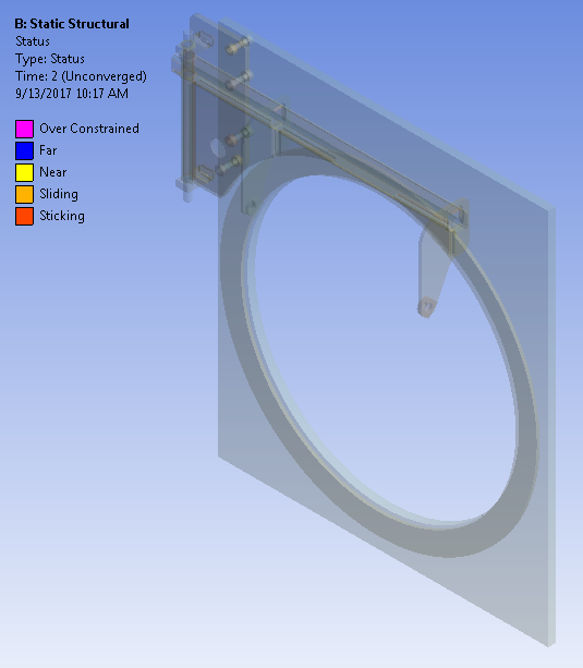
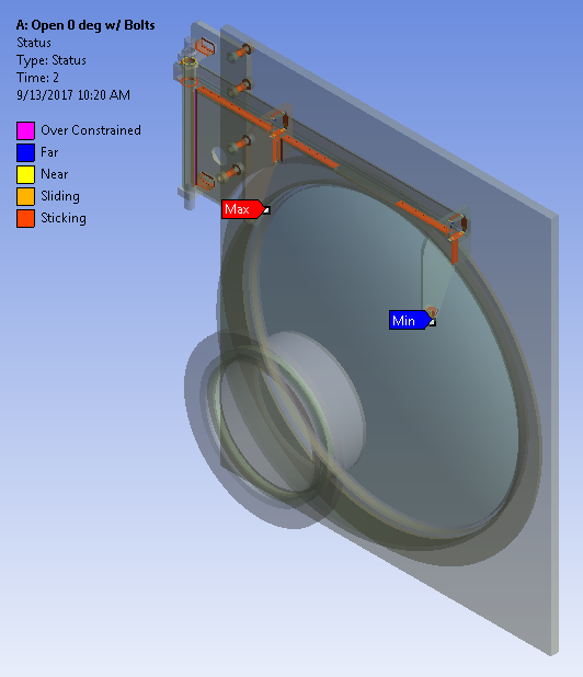
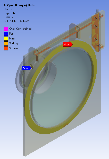
Here's what the contact tool status plot shows:

Capture_cn14gg.png


For comparison, when I do the same simulation with joints representing the contact (i.e. in a simulation not getting these crazy results), this is the results of the contact status plot:

Capture_d0vmen.png
Capture_w8dev0.png
 
The error indicates there is an unrestrained part. I assume the flying part is the colored red in your earlier picture and it is the same part you are trying to clamp with bolt preload.

Some suggestions:
1. Would it be possible to apply a temporary displacement 'support' on a small section of the 'red part' to avoid rigid body motion, apply your bolt preload, lock it, then remove the temporary support in the next time step? This should help keep the model from flying.
2. I noticed the red part has a thin face that is 'Near' (Yellow circle in this picture). Could you modify the geometry such that it is line-to-line to the contacting part?


Kind regards,
Jason
 
Hmm... Here's where I really wish I could share my model with you so you could see what it looks like.

This is a cover for the end of an HVAC chiller, and what I'm modeling is the hinge that allows the cover to be opened so the chiller's tubes can be cleaned. The large square plate in the model is the end of the chiller to which the hinge gets bolted to. If you want to compare it to the hinge on a door, the large square plate is the door jam. The bolts referenced earlier attach the "jam side" of the hinge to the plate. At this point (potentially because you've helped me fix the problems with them), they don't seem to be causing an issue. What is happening however, is that the contact connections between the "hinge pin" and the "door side" of the hinge aren't being enforced properly and as a result the "door" and the "door side" of the hinge can go flying off.

The point of all that is the only thing preventing the behavior seen here from happening in reality is the contact between the "hinge pin" and the sleeve of the "door side" of the hinge that the "hinge pin" goes into. This is relevant to the conversation about the bolts in contact because when I define a revolute joint between the "hinge pin" and the sleeve, everything stays together just fine, but when I define a contact connection between the two surfaces, they fly apart. I think the issue is that initially there is a 1/8 in clearance all the way around the pin, which means that ANSYS ignores the contact at the start of the simulation and never reconsiders it later. This is what I was trying to prevent by setting the radius of the pinball region to 0.13 in (shown in the screenshot of the frictional contact settings above), but evidently that either doesn't do what I though it did or I didn't set it correctly.
 
OP said:
ANSYS ignores the contact at the start of the simulation and never reconsiders it later
There is a vertical blue line in the picture which I assume shows the contacts are 'far' between the pin and the sleeve.

Other suggestions:
1. Increase the pinball radius (say... 1 inch).
2. In geometry, move the door such that pin and sleeve are touching near where they are expected to.


Kind regards,
Jason
 
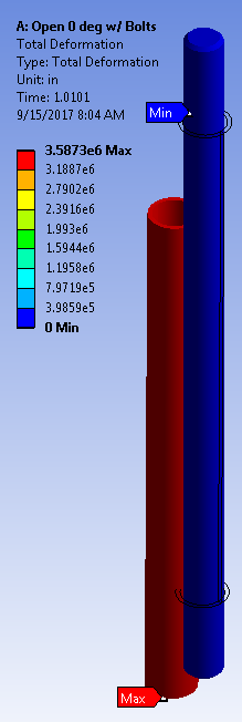
Okay, so I should have realized that the sleeve should have been in contact with the pin a while ago. That seems pretty obvious now. So having made that change and finding some parts that were not bonded as they should be, I think I'm much closer to getting this figured out. However, I'm still having problems with the contact between the hinge pin and the sleeve being ignored. I have the simulation split into two parts. The first part is where the bolts are preloaded, and during that time, I have the displacement of the sleeve constrained since I realized that it was moving during the preload step for some reason. The second part is where I apply gravitational acceleration to see the effects of the weight. At the very end of the first step, the entire sleeve is shown to be either in contact or nearly in contact with the sleeve. At the very beginning of the second step, the sleeve jumps an enormous distance away. See the images below for reference (note that I've greatly scaled the total displacement down so that the two parts will be visible when shown at the same time):

Capture_nxzgvz.png
Capture2_saryfg.png


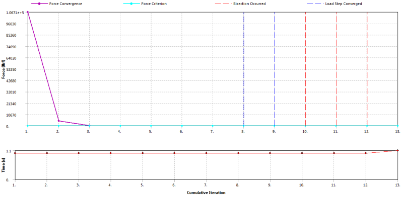
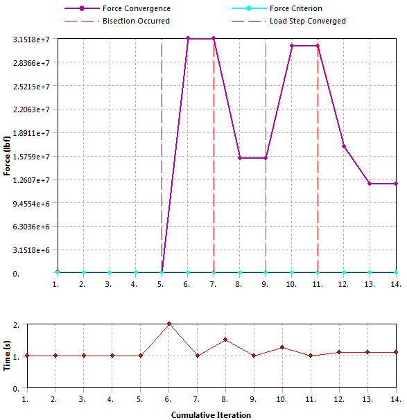
Now, to be clear, the solution has obviously not converged. Here's the force convergence plot:

Capture3_muopxi.png


Here are the error/warning messages I'm getting:

Code:
Error 	An internal solution magnitude limit was exceeded. (Node Number 406406, Body CT51EA480_G21, DOF UY) Please check your Environment for inappropriate load values or insufficient supports.  You may select the offending object and/or geometry via RMB on this warning in the Messages window.  Please see the Troubleshooting section of the Help System for more information.	Project>Model>Static Structural>Solution	Friday, September 15, 2017 7:54:07 AM
Warning The solution failed to solve completely at all time points. Restart points are available to continue the analysis. 	Project>Model>Static Structural>Solution	Friday, September 15, 2017 7:54:07 AM
Warning At least one body has been found to have only 1 element in at least 2 directions along with reduced integration.  This situation can lead to invalid results or solver pivot errors.  Consider changing to full integration element control or meshing with more elements.  Offending bodies can be identified by Right-clicking in the Geometry window and choose Go To -> Bodies With One Element Through the Thickness.  Refer to Troubleshooting in the Help System for more details.	Project>Model>Static Structural>Solution	Friday, September 15, 2017 7:54:07 AM
Warning The unconverged solution (identified as Substep 999999) is output for analysis debug purposes. Results at this time should not be used for any other purpose.	Project>Model>Static Structural>Solution	Friday, September 15, 2017 7:54:07 AM
Warning Although the solution failed to solve completely at all time points, partial results at some points have been able to be solved.  Refer to Troubleshooting in the Help System for more details.	Project>Model>Static Structural>Solution	Friday, September 15, 2017 7:54:07 AM
Warning Solver pivot warnings or errors have been encountered during the solution.  This is usually a result of an ill conditioned matrix possibly due to unreasonable material properties, an under constrained model, or contact related issues.  Check results carefully.	Project>Model>Static Structural>Solution	Friday, September 15, 2017 7:48:30 AM
Warning Contact status has experienced an abrupt change.  Check results carefully for possible contact separation.	Project>Model>Static Structural>Solution	Friday, September 15, 2017 7:47:49 AM

The reported error "An internal solution magnitude limit was exceeded" is quite strange to me. The node number is on the other side of the model and is not even close to being loaded in any significant way, so I'm not sure how a limit of any kind could be exceeded in any way.
 
I'm not sure if the suggestions I've been throwing at you are helpful. Tell me to stop if they aren't.

In addition to previous suggestions...
1. Increase your initial substeps to a bigger number (e.g. 100) for the second load step.
2. Apply displacement control to make sure contacts are engaged before swapping it with gravitational load in the following step.


Kind regards,
Jason
 
Adding contact tool under connections is a good practice to check the status of all the contacts before running analysis.
It will inform you if there are gaps between contacting surfaces.
 
Status
Not open for further replies.

Part and Inventory Search

Sponsor