Continue to Site

Eng-Tips is the largest engineering community on the Internet

Intelligent Work Forums for Engineering Professionals

  • Congratulations waross on being selected by the Eng-Tips community for having the most helpful posts in the forums last week. Way to Go!

Modelling Band Beams in Ram Concept 2

Status
Not open for further replies.

FreshMan2020

Structural
May 7, 2020
24
Hi all, I have question in regard to modeling band beams in Ram Concept.
Basic Info:
8.5m x 8.5m grid with 2400mm*500mm (D) running in longitude direction.
Band beams are defined as standard beam element with 'meshed as slab' option unticked while slab is defined as one way slab.
Longitude column strip is set to be T-Beam with 'design column strip for column + middle strip resultants' selected. Latitude design strip is set to be one way slab rectangle.


Questions
I want to design slab together with band beams in Ram Concept (strength and service including long term deflection).
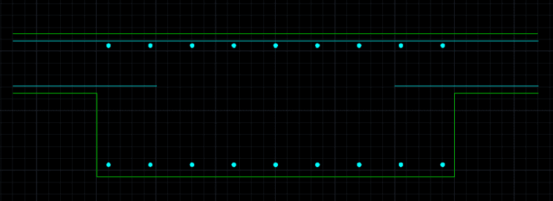
The reinforcement plan in Ram Concept produce 'unwanted' latitude bottom reinforce in band beam area (refer below pic 1). I understand that from analysis results there will be moment in that area in that direction which is why reinforcement is produced. However, I want the band beam to be design as 'one way' without transverse bars detailed as below (pic 2). (no even ligs unless the concrete shear capacity fail). So what do I do in Ram Concept to achieve what I want?

q_gtx1e2.png
pic 1 : Unwanted latitude bottom bar in band beam

1122_tac70t.png
pic 2: actual detail I want to design for slab-to-beam

Thank you.
 
Replies continue below

Recommended for you

FreshMan2020 said:
...Just expected the latitude design strip would recognize where beam is and not apply the design rule for slab in that area....
Concept and pretty much any software for that matter are only going to do what you tell it to do or what the programmers told it to do. In this instance using the design strip you told the program to design this section as a one-way slab. Once you read Concept's manual you'll see that the programmers told the program that there is no difference between a modelled beam and slab, both are meshed as concrete areas one may just have the default stiffness properties altered to get more favorable behavior.

My Personal Open Source Structural Applications:

Open Source Structural GitHub Group:
 
I know this hasn't been mentioned but it is critical in Concept to make sure to consider next axial force when your slab has beams, steps, etc. The net axial force that developed from the change in geometry is large - this obviously affects your shear design, of which you do not want to mess up with.

Assigning a span to be designed as a beam, merely changes the code checking from the slab chapter to the beam chapter. Thus, it will enforce d/2 stirrups spacing, and all the other minimums required of beams. FEM meshing of beam and slab elements is generally the same. You could also model the drop beams as thicker slab areas, and your spans could be set to design as a Beam. It is mostly a matter of convenience in modeling and meshing priorities.

I understand people questioning using Concept for such a 'regular' design, but you need to think about the future. It is MUCH easier to flesh out the inner-workings of the program, of which are vast, when working on a simple model. You don't want to be leaning the program simultaneously while designing, say, a complex transfer deck supporting 10 stories.

Also, rely on Bentley support and the Bentley Communities. Seth Guthrie at Bentley is incredibly helpful and fast to respond in the Community. I have been using Concept for the last 7 years, grown to like it a lot, rely on it for complex designs, and still regularly communicate with Seth on weird things that pop up.

-Mac
 
@FreshMan2020

RAM proposes the bottom reinforcement because you have design strips cutting across the band beam (as others have already pointed out) - you can go to "Design Strips - Perspective View" to view these design stops in a 3-D view. It is important to understand that RAM Concept performs design checks across every single one of these strips.

If you really want to get to the bottom of why RAM inserts any particular set of rebar I suggest you "audit" the relevant deign section (I suggest that you refer to the manual to see how to do this). The audit report gives you a detailed readout of what exact calculations are carried out and tells you what code clauses get triggered. It is difficult to say for sure why you get this bottom rebar without knowing specifics of your setup and what design code you are designing to.

Having said that I can speculate that this reinforcement is there because of the minimum ductility requirements. These requirements come under different names in different countries/codes, but in basic terms they make sure that you supply some minimal amount of rebar to the part of your section that is in tension to ensure some amount of minimal strength and ductile mode of failure.

The thing with banded PT systems is that the band beams can experience positive flexure in their secondary direction - this can be either in transfer stage where PT is stressed or else can occur generally during in-service conditions. The reality is that the bands do flex in two directions and as a result they should contain some minimal amount of reinforcement (as a result of the aforementioned ductility clauses). This usually flies under the radar and engineers can provide for it unintentionally via specifying shear ligs (as some have already mentioned). Reinforcement of this kind is not "unwanted" but rather it is common practice (at least in my experience so far).

I design regularly in RAM Concept and sometimes I fancy thinking that I know what I am up to. Let me know if you need some specific advise to the tune of "...how do I do thing A...".
 
Status
Not open for further replies.

Part and Inventory Search

Sponsor