Continue to Site

Eng-Tips is the largest engineering community on the Internet

Intelligent Work Forums for Engineering Professionals

  • Congratulations KootK on being selected by the Eng-Tips community for having the most helpful posts in the forums last week. Way to Go!

Modelling wall on beam issue.

Status
Not open for further replies.

aenger

Structural
Nov 19, 2017
17
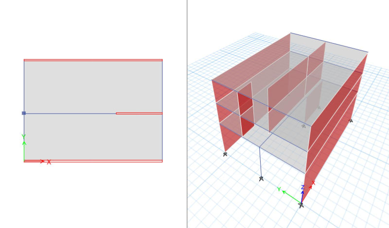
Guys. I have this simply structure: concrete wall on transfer beam as blow.

0_rj69fn.jpg

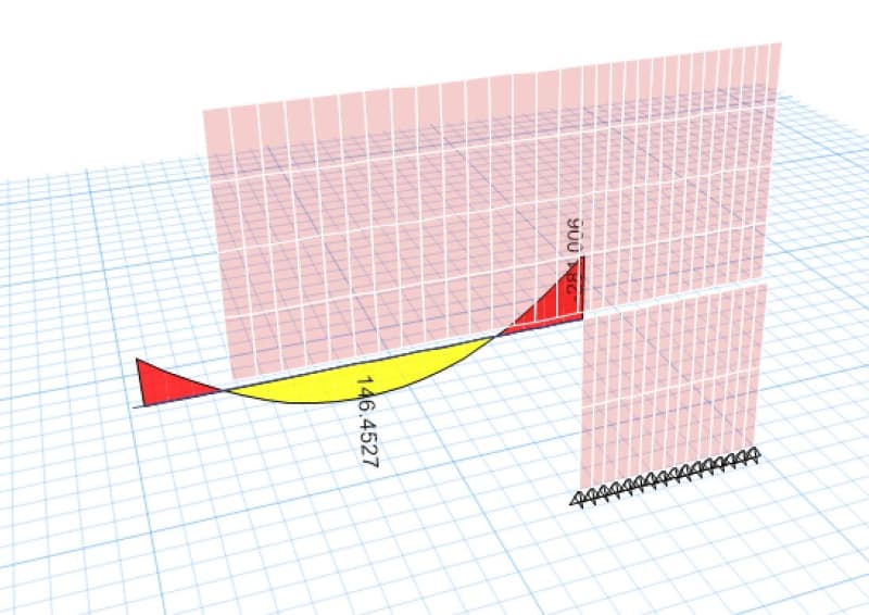
After running the model. I got this M3 diagram for frame as below.
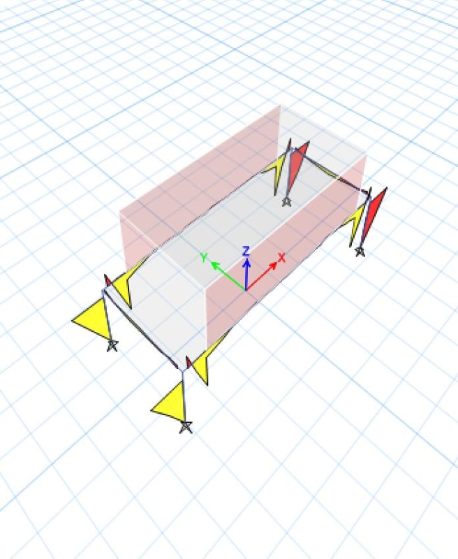
1_dayxgh.jpg


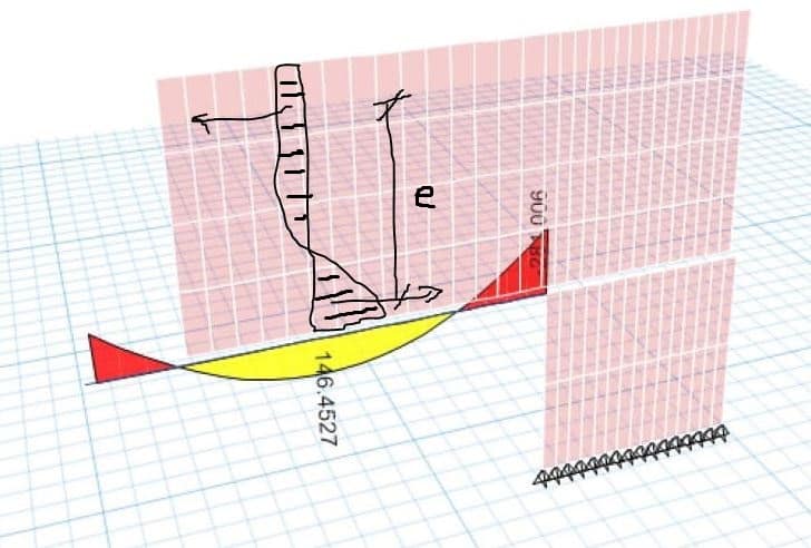
If I change the membrane f12 stiffness of the wall to be say 0.01 I got the diagram that I expected.
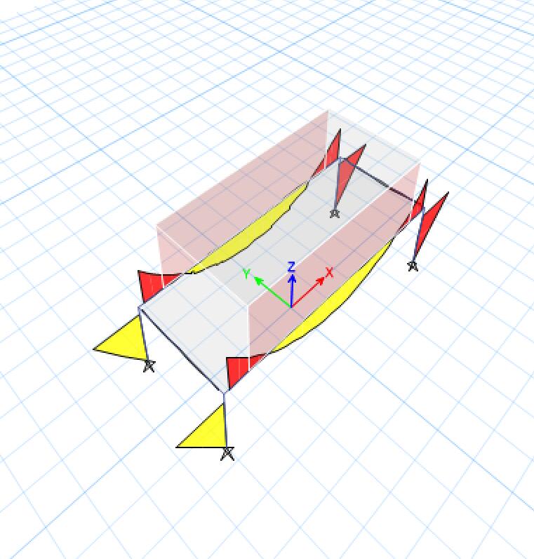

2_jca54f.jpg


So my question is which one is the correct one and why?

considering the walls do have in-plane stiffness and it is gonna work together with the beam as a deep wall and the strut-and-tie behaviour happens at their intersections, which match the first diagram (please correct me if I am wrong).So it seems to me that changing this f12 figure will not produce the real behaviour of the structure. But on the other hand, if I don't run the FEA I will simply design the beam by adding line load from the wall above, which will give me the later result. So does that mean the later one is correct? (If so, does that mean we need to change this modifier everytime when the walls are going to be transferred by beam/slab? ) What do you guys normally do?

Thank you.
 
Replies continue below

Recommended for you

if you use second option you are on the safe side because you will have more reinforcement in the beam, but in that case you are assuming that the wall has fully cracked.
you can use second option but provide enough vertical reinforcement to take shear between beam and the wall, in that case you are basically doing both systems.
 
I agree with Tommy, I would be enveloping the design, i.e. design the wall reinforcing as if it spans (option 1), and provide beam reinforcement as if the wall does nothing (option 2).
 
This is a tricky question, the "reality" of the behavior (based on stiffness and the FEM results) seems to be different than the traditional methods we would have done by hand. I tend to agree with others here in that it probably makes the most sense to envelope the design.
 
Thanks guys.

Apart from this wall stiffness issue. There is actually one more thing that confused me.

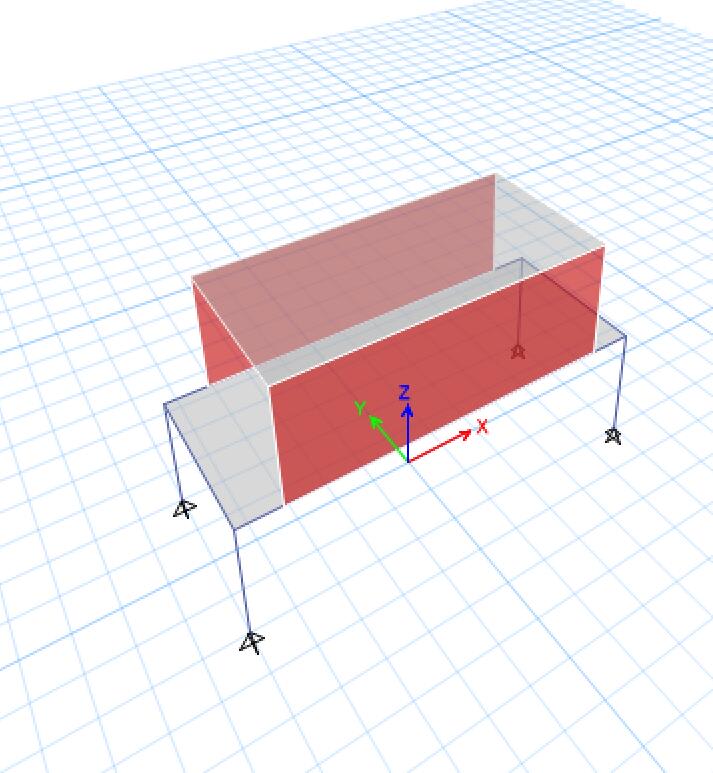
Below is the structure I have. The transfer beam connects to a column and a wall, support two level walls above with 0.5m eccentricity. The structure is 10meters in short span and the beam is near 10 meters long. Before I run the model, I did a hand cal for the beam, getting the line load from walls and slab above and then apply to the beam. After running the model. I got a extremely small bending moment for the beam compared to the one I comp by hand. This time no matter I change the f12 of wall or not, this moment from FEA is always way smaller than hand cal.

I am wondering what cause this.
Is it because most loading transfer to external walls as there are stiffer? (In this case does that mean the beam does work as support for the slab and the slab will thus have more deflection and bending moment?)

Or is it because the program treats the wall below working together with the wall above like a cantilever beam (even there is a eccentricity) so most of the loading from wall above go to the wall under? Can I reply on this result? If I use hand cal I will need a very deep beam.

Whats your guys' thoughts?


Thanks in advanced.


12_l3imth.jpg

133_nwhlpa.jpg
 
I don't disagree with any of the above but, in a production environment, I would:

- Design the beam assuming no composite action with the wall.

- Make the beam nice and stiff precisely because I know that it will be supporting a rigid wall that I don't want to see all cracked up in service.

- Not bother to design the wall for composite behavior. It would be time consuming done properly. Deep beam action and all that jazz.

One thing to consider here is that the model that assumes full composite action will generate very high tensions forces in the wall dowels near the ends of the walls. Basically localized moment connections between wall and beam. Strain, and likely yielding in your wall dowels will tend to soften up the rigidity of the connection and steer things back towards a more traditional, non-FEM load distribution.

I like to debate structural engineering theory -- a lot. If I challenge you on something, know that I'm doing so because I respect your opinion enough to either change it or adopt it.
 
hi aenger,

yes your wall ist taking a part of the load, check the normal horizontal stresses in wall, you should get something like this
1_xddo3w.jpg


p.s. if you wanna use wall as a deep beams dont forget that you need extra reinforcement to "hang" the loads of the lower slab into the wall
 
Thumbs up for the questioning attitude regarding your FEM results. How stiff are the 2nd story and roof slabs in bending? They might be taking some of the interior wall load out to the exterior walls. Try setting the bending stiffness of those slabs to zero and see if the load on the transfer beam increases.
 
Thanks Kootk, Tommy and bones.

Yeah. I have also checked the pier axial force and the wall below takes most of the loading. The thing is I don't want it that way and I don't think it will work that way. Even if I wanna make it work that way that will be hard because like I said the walls do not line up. So how do I adjust in model to avoid this?

They are 200mm slab. I changed the slab from shell to membrane but doesnt make a big difference and I think it is mostly affected by the wall below. I checked the reaction of the column that support the beam and it was only half as I cal by hand.
 
Oh ok yea that makes sense. The wall load above is being pulled across to the partial wall below via arching action. If you can turn on the axial force contours you should be able to visualize that load path.
 
aenger said:
The thing is I don't want it that way and I don't think it will work that way.

I'm inclined to disagree. With such a slight offset between walls, I think it entirely plausible that much of the load will be transferred to the wall below. And that, of course, may cause shear problems in your slab.

You might look into the virtual outrigger concept as that's probably a bit of what you'll have going on here whether you want it or not: Link

One way to exert some control over the behavior of the wall might be to introduce a vertical control joint in the upper wall near the interior end of your transfer beam.

I like to debate structural engineering theory -- a lot. If I challenge you on something, know that I'm doing so because I respect your opinion enough to either change it or adopt it.
 

Hi KootK, thanks for the link. I get the idea of increasing the horizontal element stiffness to transfer lateral load to outer vertical elements. But still in here, if I design it like what the program tells me. the force on the beam will be very small and thus requires a way smaller beam and I am not very confident on this to be honest (mostly because of the connection). I am considering running a band beam to cover the eccentricity. Is there anything else (like connections etc.) that I need to consider if I use the result from FEA?
 
aenger said:
I am considering running a band beam to cover the eccentricity.

Love it.

aenger said:
Is there anything else (like connections etc.) that I need to consider if I use the result from FEA?

This is too general of a question for me to be able to provide a very meaningful answer I'm afraid. This is the best that I can do without more specific direction:

- Get your force set from FEM.
- Modify your FEM force set to reflect your judgement with respect to any possible deficiencies. Consider enveloping some actions.
- Design for your force set(s) completely, neglecting no part of the load path.

Of course, you didn't need some condescending internet stranger to tell you all of that.
 
Status
Not open for further replies.

Part and Inventory Search

Sponsor