aenger
Structural
- Nov 19, 2017
- 17
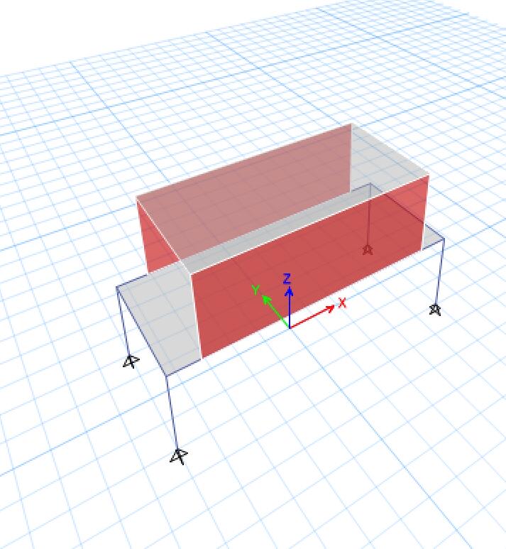
Guys. I have this simply structure: concrete wall on transfer beam as blow.
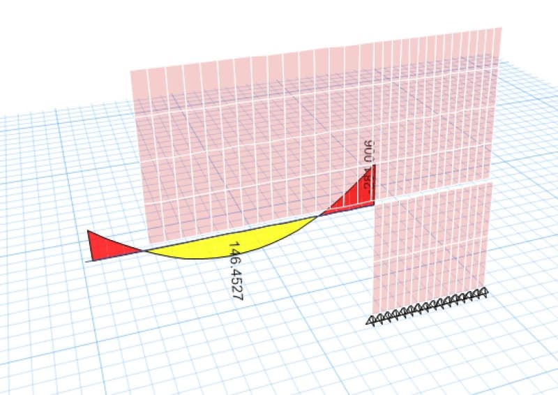
After running the model. I got this M3 diagram for frame as below.
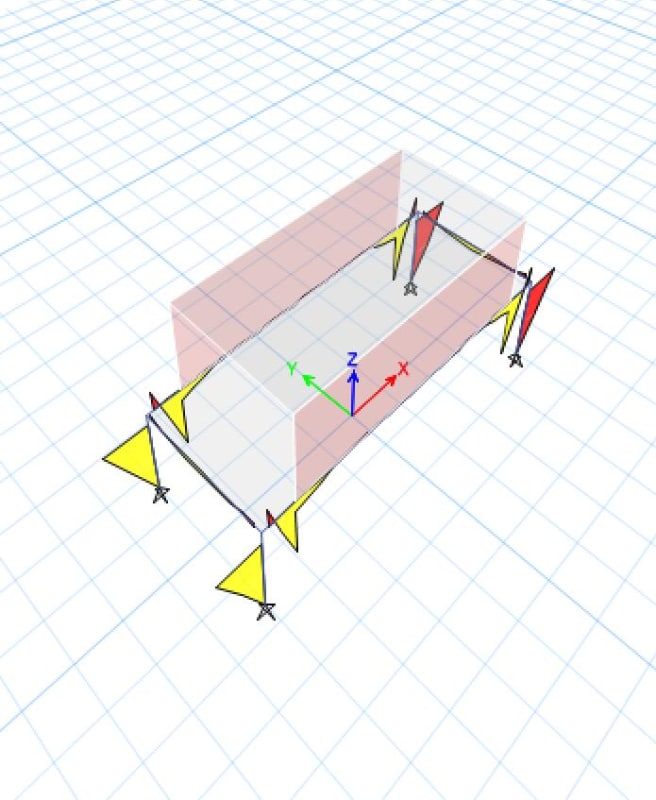
If I change the membrane f12 stiffness of the wall to be say 0.01 I got the diagram that I expected.
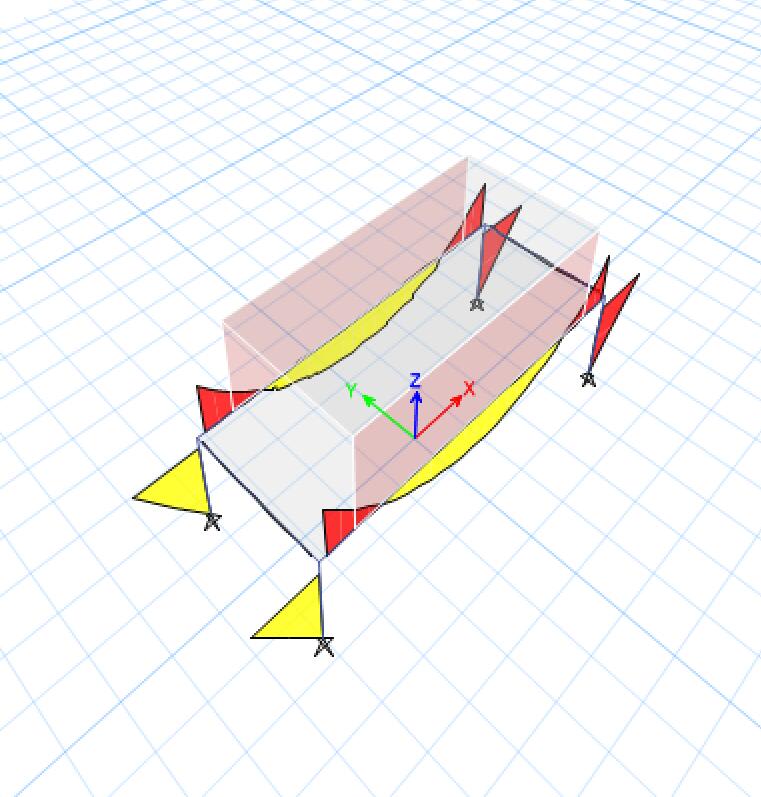
So my question is which one is the correct one and why?
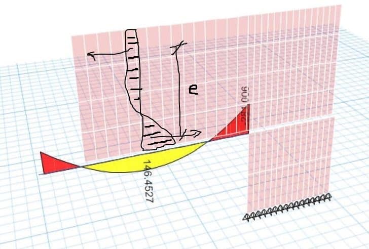
considering the walls do have in-plane stiffness and it is gonna work together with the beam as a deep wall and the strut-and-tie behaviour happens at their intersections, which match the first diagram (please correct me if I am wrong).So it seems to me that changing this f12 figure will not produce the real behaviour of the structure. But on the other hand, if I don't run the FEA I will simply design the beam by adding line load from the wall above, which will give me the later result. So does that mean the later one is correct? (If so, does that mean we need to change this modifier everytime when the walls are going to be transferred by beam/slab? ) What do you guys normally do?
Thank you.

After running the model. I got this M3 diagram for frame as below.

If I change the membrane f12 stiffness of the wall to be say 0.01 I got the diagram that I expected.

So my question is which one is the correct one and why?
considering the walls do have in-plane stiffness and it is gonna work together with the beam as a deep wall and the strut-and-tie behaviour happens at their intersections, which match the first diagram (please correct me if I am wrong).So it seems to me that changing this f12 figure will not produce the real behaviour of the structure. But on the other hand, if I don't run the FEA I will simply design the beam by adding line load from the wall above, which will give me the later result. So does that mean the later one is correct? (If so, does that mean we need to change this modifier everytime when the walls are going to be transferred by beam/slab? ) What do you guys normally do?
Thank you.

