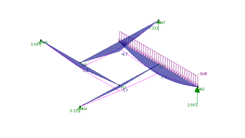
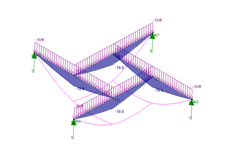
I was looking at the steel quiz in the 10/17 issue of MSC. I was able to pick up the problem quickly as I'm sure others have. However, I had a slightly different answer, I came to the conclusions that the framing plan shown had beams that required themselves for support and therefore would not work. However the article simply states that the configuration is difficult to erect. Is the framing plan shown even structurally stable utilizing simple structural theory?
Navigation
Install the app
How to install the app on iOS
Follow along with the video below to see how to install our site as a web app on your home screen.
Note: This feature may not be available in some browsers.
More options
Style variation
-
Congratulations MintJulep on being selected by the Eng-Tips community for having the most helpful posts in the forums last week. Way to Go!
You are using an out of date browser. It may not display this or other websites correctly.
You should upgrade or use an alternative browser.
You should upgrade or use an alternative browser.
Modern Steel Construction Steel Quiz 12
- Thread starter SteelPE
- Start date
- Status
- Not open for further replies.
SteelPE,
The answer in the link talks about the need for temporary support, which is what you are saying is it not?
The answer in the link talks about the need for temporary support, which is what you are saying is it not?
-
2
- #4
It's stable. The deflection profile may be a Bessel function or something equally bizarre but it's stable. There's actually an entire branch of wood frame architecture devoted to this kind of thing: Reciprocal Architecture.
I like to debate structural engineering theory -- a lot. If I challenge you on something, know that I'm doing so because I respect your opinion enough to either change it or adopt it.
I like to debate structural engineering theory -- a lot. If I challenge you on something, know that I'm doing so because I respect your opinion enough to either change it or adopt it.
- Thread starter
- #7
- Thread starter
- #8
OK, I took a quick look at your paper KootK and most of the framing that was shown would have an axial compression load associated with the framing. What was shown in MSC would I would guess you would end up with a catenary (tension) load. I can see how it would work, but I'm not daring enough to do it.
canwesteng
Structural
I don't think it's stable without some kind of differential elevation in the beams, similar to the reciprocal framing in kootk's link. In FEA you'll get an instability warning, in practice it probably deflects into a funnel shape and destroys your floor and ceiling finishes.
TehMightyEngineer
Structural
You could possibly make it stable via fixed beam ends putting torsion into the supporting beams; obviously not least cost but it would make the deflection calculations easier.
Professional Engineer (ME, NH, MA) Structural Engineer (IL)
American Concrete Industries
Professional Engineer (ME, NH, MA) Structural Engineer (IL)
American Concrete Industries
- Conventional FEM chokes on this because it's (obviously) non-linear and recursive. No great surprise there.
- You tend to see this in sloped members simply because you tend to see this in roofs. Architects are usually a good deal less about the aesthetics of it in the underside of a floor. Also, you kinda need the oculus business for full dramatic effect. That's not unheard of in floors but pretty rare.
- I don't believe that axial/membrane effects are required for stability. If you've got a competent tension ring that'll certainly help. With no tension right, the slope exacerbates problems and lateral spread rears its ugly head.
- From a stability perspective, I believe this to be okay by inspection based on this observation: by definition, nothing here "grows without bound". The contributions to flexure and deflection get progressively smaller as you cycle round. Nothing runs away/amok on you.
- If you've got a vibration sensitive occupancy, that definitely warrants some attention.
- If you've got rain or concrete ponding potential, then there's a stability issue there. But that's a different animal and, other than trickier math, is little different than ponding issues in normally framed systems.
- This is actually quite a common morphology in old school heavy timber structures, particularly in the NE. Barns and churches where they mount a pergola on top and want no obstruction below. Back in my wood truss design days, I used metal plate wood connected trusses reciprocally to mimic these structures in certain applications.
- A useful way to think of these systems is as two, crossing beams, each constructed in two pieces that are moment spliced in a peculiar fashion.
I like to debate structural engineering theory -- a lot. If I challenge you on something, know that I'm doing so because I respect your opinion enough to either change it or adopt it.
slickdeals
Structural
There was a similar article in 2007 in Structure Magazine.
Nice! There's a paper for darn near everything these days.
I like to debate structural engineering theory -- a lot. If I challenge you on something, know that I'm doing so because I respect your opinion enough to either change it or adopt it.
I like to debate structural engineering theory -- a lot. If I challenge you on something, know that I'm doing so because I respect your opinion enough to either change it or adopt it.
-
1
- #14
For what it's worth, I just created a quick RISA 3D model and it seems to work just fine.
Not saying I'd ever try to build this but I believe it does work.
The tough part for me to reconcile is "chasing" the load around the ring. In my first model (with only one distributed load) half the reaction gets passed to the connected beam over and over and over until it effectively is zero.


Not saying I'd ever try to build this but I believe it does work.
The tough part for me to reconcile is "chasing" the load around the ring. In my first model (with only one distributed load) half the reaction gets passed to the connected beam over and over and over until it effectively is zero.


DaveAtkins
Structural
Years ago, I actually saw a roof built out of glu-lam members which looked exactly like DETstru's model. I remember staring at it for quite sometime![[ponder] [ponder] [ponder]](/data/assets/smilies/ponder.gif)
DaveAtkins
![[ponder] [ponder] [ponder]](/data/assets/smilies/ponder.gif)
DaveAtkins
JoshPlumSE
Structural
I was skeptical, but I built the same kind of model as DETstru and it worked. The deflection really wasn't that large either. I was very careful to make sure that I didn't have any weird torsional interaction between members. And, that's not including any kind of system non-linearity. So, it appears that it is a stable system... Though a very, very weird one.
Note:
While you can create these type of model in a general purpose program (like RISA-3D) I don't believe you could create it in a program like RISAFloor or RAM or such. Very difficult to track tributary areas for live load reduction or such for a funky framing system like this.
Note:
While you can create these type of model in a general purpose program (like RISA-3D) I don't believe you could create it in a program like RISAFloor or RAM or such. Very difficult to track tributary areas for live load reduction or such for a funky framing system like this.
Guest262653
Geotechnical
Reading this discussion, I made the mistake of googling "plane reciprocal frame structures". Now I have no free time... Thanks a lot. ![[bigsmile] [bigsmile] [bigsmile]](/data/assets/smilies/bigsmile.gif)
Just found the following links:
And the following book:
![[bigsmile] [bigsmile] [bigsmile]](/data/assets/smilies/bigsmile.gif)
Just found the following links:
And the following book:
- Status
- Not open for further replies.
Similar threads
- Question
- Replies
- 6
- Views
- 11K
- Replies
- 7
- Views
- 11K
- Replies
- 0
- Views
- 7K
- Replies
- 3
- Views
- 8K
- Replies
- 5
- Views
- 10K
