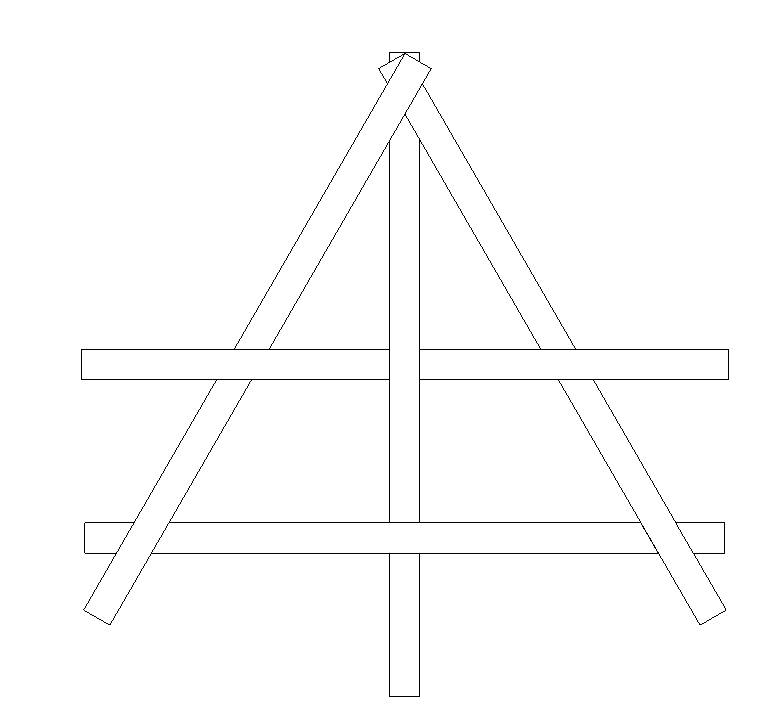
I was looking at the steel quiz in the 10/17 issue of MSC. I was able to pick up the problem quickly as I'm sure others have. However, I had a slightly different answer, I came to the conclusions that the framing plan shown had beams that required themselves for support and therefore would not work. However the article simply states that the configuration is difficult to erect. Is the framing plan shown even structurally stable utilizing simple structural theory?
Navigation
Install the app
How to install the app on iOS
Follow along with the video below to see how to install our site as a web app on your home screen.
Note: This feature may not be available in some browsers.
More options
Style variation
-
Congratulations cowski on being selected by the Eng-Tips community for having the most helpful posts in the forums last week. Way to Go!
You are using an out of date browser. It may not display this or other websites correctly.
You should upgrade or use an alternative browser.
You should upgrade or use an alternative browser.
Modern Steel Construction Steel Quiz 12
- Thread starter SteelPE
- Start date
- Status
- Not open for further replies.
-
1
- #41
TehMightyEngineer
Structural
Also redundancy. The structure is the epitome of non-redundant where failure of one member is guaranteed to result in a catastrophic collapse of the entire reciprocal frame. I'd only do this if it had an architectural feature and was skookum as frig.
Professional Engineer (ME, NH, MA) Structural Engineer (IL)
American Concrete Industries
Professional Engineer (ME, NH, MA) Structural Engineer (IL)
American Concrete Industries
I love the photos and enthusiasm, but I`m still not on board with the stability argument.
I've only seen one of these "in the wild" and the deflections were enormous. It was a wood framed structure, and too long ago to remember the specific spans or member sizes.
I ran a RAM elements analysis and it didn't show any problems and didn't show any axial forces or weak axis bending. Really, it only convinced me that RAM isn't a proper tool for this type of problem.
Each of the physical models shown here, and the photos of the shelter structure, show a significant overlap between the framing members. If there is any slip between these members it wouldn't matter and you can develop friction between these joints to help minimize slip.
What happens with a series of wood beams to nailed or end nailed together? There is no potential to develop axial resistance and the consequences of slip are much more severe.
With steel connections, you`ll get some axial capacity from a standard shear plate connections and maybe that's enough to provide stability, but I don't think its inherently stable.
GregLocock
Automotive
The book KootK linked to emphasises that the design of the notches and joints is crucial to success. To be honest the examples given where the joints are twisted wire (frapping as we called it in the Scouts) look a lot more robust, easier and uglier than the minimalist notched style used by the Japanese.
Cheers
Greg Locock
New here? Try reading these, they might help FAQ731-376
Cheers
Greg Locock
New here? Try reading these, they might help FAQ731-376
bridgebuster
Active member
The model posted by Detstru has been around for more than 40 years. If anyone has an old copy of Beer and Johnson Statics and Dynamics textbook, it's there.
TehMightyEngineer
Structural
atrizzy said:I'm trying to mentally calculate the reactions if only one of the beams was loaded and it's kind of driving me crazy...
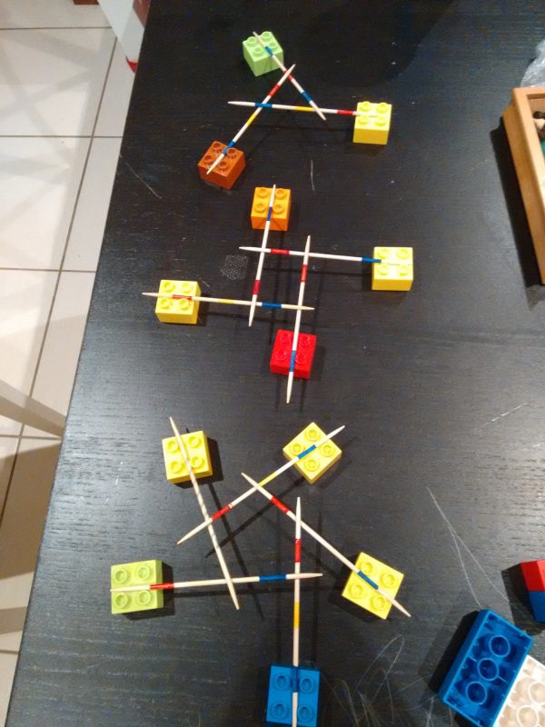
This was actually why I made my little chopstick model. It's actually fairly simple once you think about it but it does have "second-order" effects. Each beam acts simple span and thus a load on beam #1 causes a reaction of some percentage onto beam #2, that loads some percentage onto beam #3, then that loads back beam #1. Thus, you need to run multiple iterations to get the true load but the actual math is just simple span beams.
Professional Engineer (ME, NH, MA) Structural Engineer (IL)
American Concrete Industries
-
1
- #48
Doing the iteration by hand, you find that you come to 99% of the reaction after the second iteration.
With one beam uniformly loaded in a system of four beams connected at their midpoint (like the DETstru model, I think) each reaction around the perimeter is half the adjacent reaction. (Look at the reactions in the first DETstru model above)
So, you'd expect the reaction to be 0.5*W in a simply supported beam. In this* reciprocal system, the reaction at the loaded beam is 0.533*W = 1/2W + 1/32W + 1/512W + ...
*edit: the summation applies to this geometry
TME said:but it does have "second-order" effects.
I believe not. I stated this myself at first but later retracted it after all the successful RISA results started rolling in. As I mentioned previously, I believe all the "load chasing" to be no more second order than the remainder chasing in moment distribution. Just business as usual with an indeterminate structure organizing itself to resist load. This is a minor clarification but an important one I think. At least is it for me as I was wrong headed about it initially.
I like to debate structural engineering theory -- a lot. If I challenge you on something, know that I'm doing so because I respect your opinion enough to either change it or adopt it.
TehMightyEngineer
Structural
KootK said:remainder chasing in moment distribution
This is a better term of what I was trying to describe, hence why I put "second-order" in quotes as it's not really second order.
kipfoot said:Doing the iteration by hand, you find that you come to 99% of the reaction after the second iteration.
Very neat! I'm amazed with only 4 beams that only 2 iterations are needed but there it is. I feel this kind of mathematically demonstrates why these frames are so much stiffer than I would expect at face value.
Professional Engineer (ME, NH, MA) Structural Engineer (IL)
American Concrete Industries
If you think about it as an inner ring of memebers that that are all pin connected. This ring is then connected to outer members. The connection from the inner ring to the outer members is a moment connection. Makes sense that way.
TME said:I put "second-order" in quotes as it's not really second order.
Ahh... my bad. I didn't register the significance of the air quotes. Which is odd as I tend to overuse that device myself.
I like to debate structural engineering theory -- a lot. If I challenge you on something, know that I'm doing so because I respect your opinion enough to either change it or adopt it.
Guest262653
Geotechnical
Here are my tests, with 3, 4 and 5 elements.
Now my wife and kids think that I'm a nerd. They're probably right.

Now my wife and kids think that I'm a nerd. They're probably right.

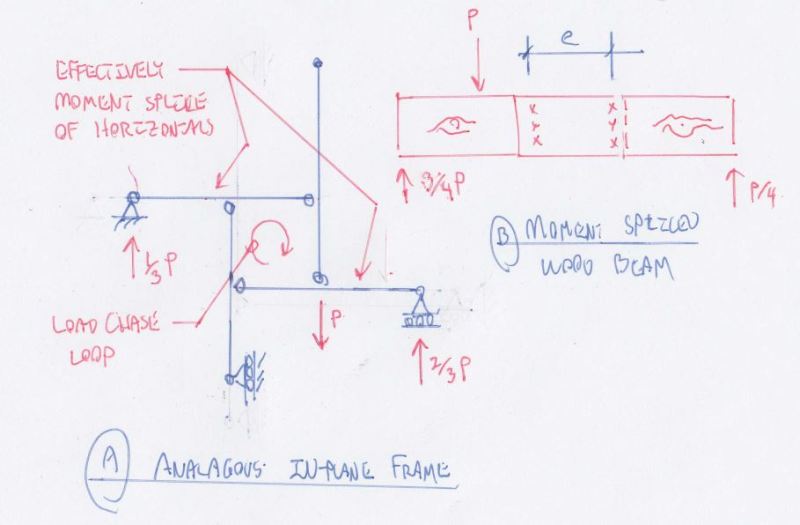
What I find most interesting about this is our physiological reaction to what seems to be effectively little more than linear elastic load distribution in an indeterminate structure (erection / vibration / redundancy excepted). For consideration, I've created what I believe to be an analogous in plane model. Does that raise anybody's stability hackles? I've also compared the system to a moment splice in timber to try and drive home what I believe to be a fundamental characteristic of these things.
In the model below, I've intentionally stripped the boundary conditions down to as few as I believe can be had while keeping the thing stable.

I like to debate structural engineering theory -- a lot. If I challenge you on something, know that I'm doing so because I respect your opinion enough to either change it or adopt it.
In the model below, I've intentionally stripped the boundary conditions down to as few as I believe can be had while keeping the thing stable.

I like to debate structural engineering theory -- a lot. If I challenge you on something, know that I'm doing so because I respect your opinion enough to either change it or adopt it.
This is pure conjecture but I wonder if we're simply bad at thinking about grillages. Most of us spend most of our time investigating and thinking about in plane models. I did some grillage stuff in college and haven't looked at a grillage of any complexity since.
I like to debate structural engineering theory -- a lot. If I challenge you on something, know that I'm doing so because I respect your opinion enough to either change it or adopt it.
I like to debate structural engineering theory -- a lot. If I challenge you on something, know that I'm doing so because I respect your opinion enough to either change it or adopt it.
I remember when I was a kid, my Mom doing this with our silverware. It was a puzzle you had to figure out.
You put the four knives flat in the formation we're all familiar with now (support the end of each knife with an upside down cup). Then you put an upside down bowl over the square made by the knives to hide how they interlock.
You show that to someone, then tell them to look away while you disassemble it. See if they can figure out how to assemble it.
I guess my mom would've made a top notch structural engineer
A similar application my mom taught me was ninja "bombs" made out of popsicle sticks.
You throw them against something (your brother's head for example) and they explode on impact. And by explode I mean their strain energy due to bending is converted into kinetic energy.
So yeah, you could say my Mom is the coolest.

You throw them against something (your brother's head for example) and they explode on impact. And by explode I mean their strain energy due to bending is converted into kinetic energy.
So yeah, you could say my Mom is the coolest.

- Status
- Not open for further replies.
Similar threads
- Question
- Replies
- 6
- Views
- 10K
- Replies
- 0
- Views
- 7K
- Replies
- 3
- Views
- 8K
- Replies
- 5
- Views
- 10K
- Replies
- 2
- Views
- 11K

