I was looking at the steel quiz in the 10/17 issue of MSC. I was able to pick up the problem quickly as I'm sure others have. However, I had a slightly different answer, I came to the conclusions that the framing plan shown had beams that required themselves for support and therefore would not work. However the article simply states that the configuration is difficult to erect. Is the framing plan shown even structurally stable utilizing simple structural theory?
Navigation
Install the app
How to install the app on iOS
Follow along with the video below to see how to install our site as a web app on your home screen.
Note: This feature may not be available in some browsers.
More options
Style variation
-
Congratulations TugboatEng on being selected by the Eng-Tips community for having the most helpful posts in the forums last week. Way to Go!
You are using an out of date browser. It may not display this or other websites correctly.
You should upgrade or use an alternative browser.
You should upgrade or use an alternative browser.
Modern Steel Construction Steel Quiz 12
- Thread starter SteelPE
- Start date
- Status
- Not open for further replies.
canwesteng
Structural
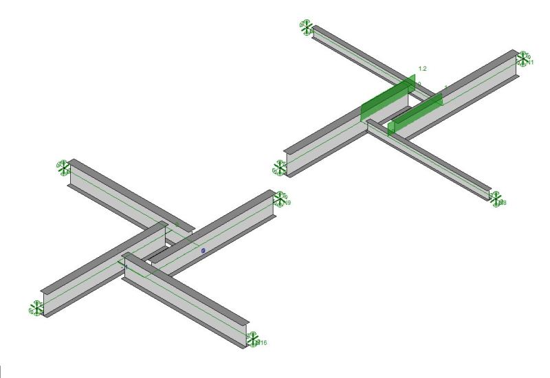
Are you releasing torsion at the ends connected to other beams? Conventionally you do not to prevent beams from spinning in space but in this case you would.
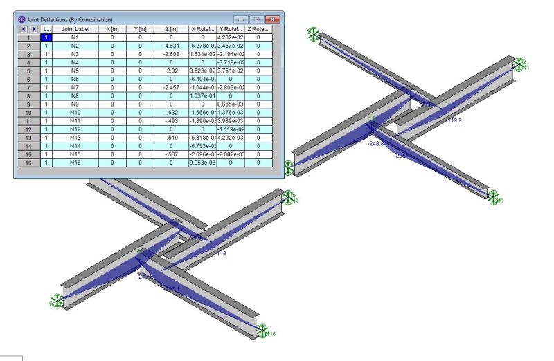
Backing off on the extreme stiffness discrepancy between models, I went to W18x35 and W8x21. Bending and torsion shown below.


I like to debate structural engineering theory -- a lot. If I challenge you on something, know that I'm doing so because I respect your opinion enough to either change it or adopt it.


I like to debate structural engineering theory -- a lot. If I challenge you on something, know that I'm doing so because I respect your opinion enough to either change it or adopt it.
I've released torsion at one end of each member which is all I'm allowed to do. Perhaps I need to break up the physical members (RISA speak) into seperate, node to node members in order to introduce more torsional release.
I like to debate structural engineering theory -- a lot. If I challenge you on something, know that I'm doing so because I respect your opinion enough to either change it or adopt it.
I like to debate structural engineering theory -- a lot. If I challenge you on something, know that I'm doing so because I respect your opinion enough to either change it or adopt it.
canwesteng
Structural
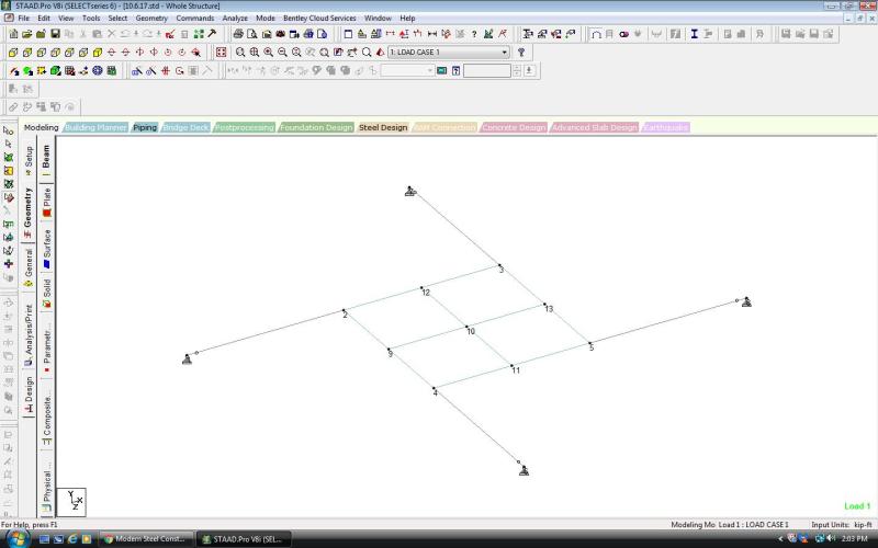
FWIW, I ran it in STAAD with roller supports, found no issues, and beam stiffness didn't affect reactions. So it would appear it is determinate.
Kootk,
If make each wood beam infinitely long, the system will still work. The wood beams will carry virtually no shear and serve to just maintain stability of the system. The wood beams will act as a make-shift moment connection between the two steel beam halves and will have 0 reaction at their supports. I think it helps to explain the behavior of the system.
If make each wood beam infinitely long, the system will still work. The wood beams will carry virtually no shear and serve to just maintain stability of the system. The wood beams will act as a make-shift moment connection between the two steel beam halves and will have 0 reaction at their supports. I think it helps to explain the behavior of the system.
That does help Jeremy and I see it the same way. Even in that hyperbolic example, however, the apparent determinacy of the system is still in play though, right?
I like to debate structural engineering theory -- a lot. If I challenge you on something, know that I'm doing so because I respect your opinion enough to either change it or adopt it.
I like to debate structural engineering theory -- a lot. If I challenge you on something, know that I'm doing so because I respect your opinion enough to either change it or adopt it.
I think about it like this. Imagine the steel beams are together and the wood beams are framed into the side. This system is determinant right? Then you slowly slide the steel beams apart until they're in the current configuration. Should the determinancy be maintained?
I mean, based on the if r = 3n its determinant, I get r = 16 (2 at each support and 2 at each hinge) and 3n = 12 which means its indeterminant but it's only a "general rule".
I mean, based on the if r = 3n its determinant, I get r = 16 (2 at each support and 2 at each hinge) and 3n = 12 which means its indeterminant but it's only a "general rule".
BAretired said:B4 reacts with W/16 + P/16 on B1, but we called that P, so:
P = W/16 + P/16
Solving, P = W/15 and the reaction of B1 can be found to be R = 8W/15
The remaining three reactions are 4W/15, 2W/15, and W/15 for B2 to B4 respectively.
The sum of all reactions is W as expected.
Yes! This shows algebraically what I did numerically with the same geometry. I determined the first reaction to be 0.533W but really it's 8W/15, which is an important distinction in this thread.
-
1
- #89
No matter how many beams there are, the system is determinate. We've been talking about four beams... But 3 beams, and 12 beams and 87 beam systems are also determinate.
Here's the proof, (which is how you should all be determining a structure's determinancy, not by running fancy computer programs! Shame!)
Let's say you have X number of beams.
There are 2X unknowns (the number of reactions is 2 per beam... Y-direction on the left end, and Y-direction on the right end of each beam).
There are also, 2X static equations. Make a free body diagram of each beam. One equation is summing the forces in the Y direction. The other equation is summing the moments about a point.
You then have a system of 2X linear equations with 2X variables.
KootK said:Nice. That's a much stronger proof and I accept it.
I got the KootK approval!
cal said:I got the KootK approval!
You certainly did. You won't often seem me post FEM as proof and, when you do, it'll often represent a personal failure of sorts. My preference is to have a working theory in hand for why something is a certain way BEFORE I do FEM to confirm it it. FEM up front usually means that I've failed in the working theory department which was the case here. And I guess there was no way around that in this instance as I appear to have been altogether wrongheaded.
I'm actually really bad at the whole quantitative indeterminacy evaluation thing. It's a gap that needs addressing. When we covered that college, I was in the midst of a really intense whirlwind romance. Very little sleep, copied homework, and sporadic class attendance for a few weeks. It's a gap that needs addressing as it comes up often here and I feel foolish being at a disadvantage on stuff that is so fundamental.
I have a LOT of structural analysis books and have actually struggled to find one that treats the subject rigorously enough for my liking. Usually just the equations, some reference to systems of equations, and a few examples. I want to be able to "feel" it if I'm going to invest the time.
I like to debate structural engineering theory -- a lot. If I challenge you on something, know that I'm doing so because I respect your opinion enough to either change it or adopt it.
TehMightyEngineer
Structural
cal91 said:...not by running fancy computer programs! Shame!
I just want to go on record saying that I remembered how to check for determinancy by hand; but I'm lazy. Thus, fancy computer programs.
Awesome proof, thanks for confirming my "engineering judgement".
Professional Engineer (ME, NH, MA) Structural Engineer (IL)
American Concrete Industries
TME said:Awesome proof, thanks for confirming my "engineering judgement".
No problem!
WARose - not sure I follow?
Not 100% sure I do either.
![[smile] [smile] [smile]](/data/assets/smilies/smile.gif)
Some of the moments goes into the beams (that run to the supports) in the 4 beam model we are talking about.....but in my analogy, all moments are in the plate in the center: Reactions from plate rotation and vertical forces run to the supports via the cables (or T/C only members).
I actually modeled this thing (i.e. a steel plate suspended) in STAAD and got some (stable) results. (And some warnings about instability unless I used fixed supports.) I also had to abandon the cables/truss members suspending it as it became too unstable. I wound up using beams....but released at the supports. (Which is like the 4 beam model.) So not sure about my original analogy.

EDIT/UPDATE: I was able to get the model above to work with the members connecting the plate to the supports designated as truss members by doing a enforced displacement at the plate corners. Sort of forcing the cables to engage (Designating the members as cable and having some initial tension didn't work.) This resulted in minimal instability.
- Status
- Not open for further replies.
Similar threads
- Question
- Replies
- 6
- Views
- 11K
- Replies
- 7
- Views
- 11K
- Replies
- 0
- Views
- 7K
- Replies
- 3
- Views
- 8K
- Replies
- 5
- Views
- 10K
