Continue to Site

Eng-Tips is the largest engineering community on the Internet

Intelligent Work Forums for Engineering Professionals

  • Congratulations waross on being selected by the Eng-Tips community for having the most helpful posts in the forums last week. Way to Go!

Moment connection in wood portal 7

Status
Not open for further replies.

struct_eeyore

Structural
Feb 21, 2017
253
Hi all,

Need a sanity check. I'm generally against moment connections in wood, but here I have to evaluate someone else's work, so obviously don't want to make too much of a fool out of myself. Please see the attached image below (or wherever it ends up). We've got an open building; the trusses rest on 2x beams which are then secured to columns with 2 thru bolts. The trusses themselves are secured to the 2x beams with 2 USP clips. Now, I can get the portals to work if I resolve the moment across all the straps, of all the trusses. The question is, will that happen in reality, or will the moment likely to want to distribute itself thru the closest straps to the posts? Also, despite the fact that the clips can carry the couple moment, do you think they are rigid enough
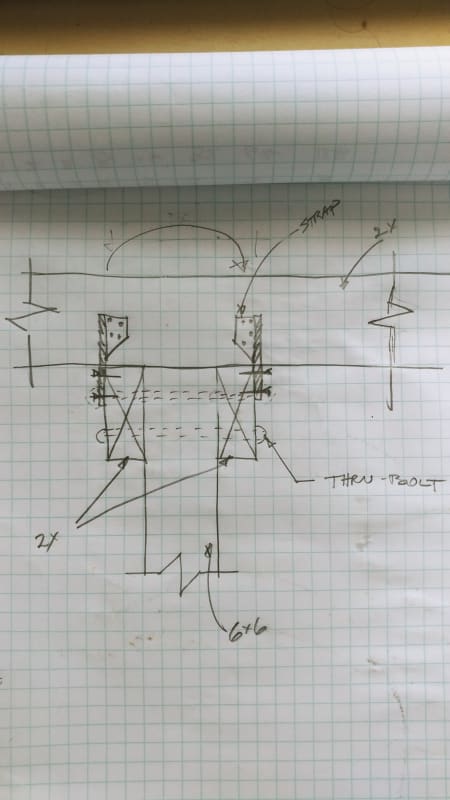
20200715_184506_qtcaoa.jpg
 
Replies continue below

Recommended for you

KootK,

That's the barrier the OP needs to overcome/consider, if full moment capacity is to be relied on.
 
retired13 said:
That's the barrier the OP needs to overcome/consider, if full moment capacity is to be relied on.

I disagree. I think OP should assume that shear friction is of no practical value in this situation and should, instead, attempt to demonstrate that whatever moment is required of the connection can be developed through the fasteners and hardware.
 
KootK,

I think this is an argument on language, or expression. "If", means the condition must be achievable, then the assumption is valid, otherwise... Without the friction, the thru bolts will displace, albeit a small amount, the full moment capacity can't be achieved. Since the OP needs joint moment strength at the joint for the system to pass the checking, further analysis/evaluation is required to determine the more realistic moment capacity for use, to evaluate the "existing" system.
 
retired13 said:
I think this is an argument on language, or expression.

Let's make it simple then. Do you believe that OP should be relying on shear friction in the connection for load resistance? That's what your comments have sounded like to me.

retired13 said:
Without the friction, the thru bolts will displace, albeit a small amount, the full moment capacity can't be achieved.

I disagree with that too. Whatever shear friction exists should be assumed to be overcome. That will produce some bolt slip but it does not mean that the required moment capacity cannot be achieved. It may or may not be achievable depending on the capabilities of the non-shear friction parts of the connection.
 
@KootK. You think the thru bolts will displace even if torqued tight with washers? I did try calling the strap manufacturer regarding any kind of test data about deformations of their anchors, however they very blatantly told me no, (or not available to public if it exists). Regarding shear transfer... this goes back to whether or not all the trusses/anchors can be used as a single member for the portal design, or just the one immediately adjacent to the posts - this will be the crux of the argument that I will be making
 
Going back to the original question, I would reject the other engineer's design based on engineering judgement. Since this is an open structure, I doubt that the framing will be inside any reasonable "building envelope." As such, it'll be susceptible to more of the expansion and contraction that KootK mentioned. Even if you can prove that the fasteners are strong enough, you still have a stiffness issue. The more movement you have in the members themselves, the less stiffness you (can) have in the joint. Less stiffness means it won't behave as a moment connection. If their analysis is a simplified, first order analysis assuming fully rigid joints, it will not be valid for this connection - regardless of your fastener and hardware connections. That means it will see more deflection/drift and induce greater second order effects and increase the demand further.

If you don't want to reject it out of hand, express your concerns for a wood moment connection, and then ask for more detailed analysis taking the things discussed above into account.
 
structee said:
@KootK. You think the thru bolts will displace even if torqued tight with washers?

Hell yes, unless somebody's willing to re-torque the bolts every time that it rains.

Even if the bolts didn't slip, would that matter? For the wood failure modes of the dowel checks, you'd still be dealing with more or less the same localized demand within the wood's fibrous structure unless you're talking about a very big washer.
 
Input very much appreciated. I feel substantially more confident negating the design. But by all means, lets continue the discussion. Back to my question about distribution of moment across parallel trusses. So you think the situation will be similar to that of column/middle strips as in 2way slab design (based on the snippet posted?) And even likely more concentrated at columns due to woods softness?
 
structee said:
So you think the situation will be similar to that of column/middle strips as in 2way slab design (based on the snippet posted?)

Absolutely.

structee said:
And even likely more concentrated at columns due to woods softness?

Probably but it's hard to say. That, particularly as you've not answered my questions:

KootK said:
1) How long are the out of plane 2X and how many connectors need to be engaged?

This here communication thing is kind of a two way street. Pony up.

The length of those 2X will have a massive impact on their stiffness and the amount of the bending bleed. That's why I asked.
 
KootK and phanEng: Great to see what you experienced guys contribute here. Just what we need - experience.
 
KtootK,

For an existing structure, if normal engineering methods can't explain an under-designed structure has stayed standing, the three possible reasons apply, 1) the structure has not yet experienced the full design load, but if confirmed otherwise, then 2) there may have other mechanism that usually discard in design for the sake of conservativism, and 3) variation in material strength.

I don't know if the OP does need the full strength provided by the combined shear friction and the tension straps, but to me, it is one option to consider. The OP has to judge if it is reliable or not though.

Note, the jamming force tends to reduce when wood shrinks. I've no data, but I believe tightening after the majority of drying shrinkage has taken place will produce a quite durable connection.
 
To retired13. Point to an example job or two when the contractor goes back and re-tightens bolts?
 
OG,

I am not positive on residential buildings, or wood works, but in steel mill, retightening is a routine maintenance. Also, as a side note, when you replace wood frames, it seems necessary for the contractor to come back to paint, in order for the paint to stick. I guess you have experienced it as well.
 
Will it withstand the first wind load... probably...

The same wind load 10 years later... possibly...

The same again in 50 years time... maybe..with excessive sway.

I really don’t like this detail and don’t care what the numbers say. How you go about fatigue in timber I’m not exactly sure, but that’s the direction you should be looking in. Regardless - It just doesn’t sit right with me and jest because the numbers presented to you appear to work does not mean you have to accept it.
 
OG said:
KootK and phanEng: Great to see what you experienced guys contribute here. Just what we need - experience.

Thanks for that, it's kind of you to say. And I agree, I like it when phamENG is on duty too. Saves me a lot of extraneous typing.

In my opinion, while the detail is probably ill-advised, it's not altogether unclever. There's a path there if it weren't for the stiffness incompatibilities that doom the thing. Done with a 12x12 piece of timber and a healthy under-utilization of the straps, you might get my stamp on it.

If a direct report brought this to me, I'd be willing to forgo the usual caning if their resume had less than a year's meaningful experience in wood.
 
Maybe is my lack of experience on wood works. But, if the connection is not required to develop moment capacity, would you still think it is a bad detail, and why?

This is an existing structure. To dig out reason why is to satisfy one's curiosity on "how", but to accept the design would be another story. I believe the OP knows well the truss needs to be strengthened, if he went through that route directly, this thread wouldn't be exist.
 
retired13 said:
But, if the connection is not required to develop moment capacity, would you still think it is a bad detail, and why?

I'd be fine with it if there were no moment capacity required of the connection other than, perhaps, the durability issues associated with using the light gauge straps outdoors if this is, indeed, outdoors.

retired13 said:
This is an existing structure

While you may well be correct, I don't believe that has been established yet. This may be an existing structure review or a internal design QC.

retired said:
I believe the OP knows well the truss needs to be strengthened, if he went through that route directly, this thread wouldn't be exist.

I don't feel that's a given as we don't know the loads, the chord size, or the bottom chord span between web panel points.
 
@Koot - those out of plane 2x's are 15' long
EDIT. And the truss span is 15' as well - so, you can think of it as an ideal small open building.
 
Thanks, 15' is not huge. While we're at it:

1) What is the depth of the 2X? Your sketch implies maybe 2x6 or 2x8.

2) Is this an existing structure or a pre-build design review?

3) Is this an outdoor structure as phamENG assumed? Not a temp structure in a convention hall or something?

4) Do we know anything about the trusses other than their span at this juncture? Chord size? Is there not a web touching down at this support as I would expect?

The trouble with these kinds of assignments is that, while you should be able to veto it based on sound engineering judgment, you really want to be able to produce some kind of numerical go/no-go if possible. To that end, I'd recommend:

1) Work out the faux, uniform, vertical loads on the 2X things assuming that they are magically rigid.

2) Use #1 to estimate the deflection of the center of the 15' 2X things.

3) Ask yourself if those kinds of movements would make sense given that one would like to not rupture any of the straps nor fracture the truss bottom chord.
 
Status
Not open for further replies.

Part and Inventory Search

Sponsor