Continue to Site

Eng-Tips is the largest engineering community on the Internet

Intelligent Work Forums for Engineering Professionals

  • Congratulations waross on being selected by the Eng-Tips community for having the most helpful posts in the forums last week. Way to Go!

Moment connection in wood portal 7

Status
Not open for further replies.

struct_eeyore

Structural
Feb 21, 2017
253
Hi all,

Need a sanity check. I'm generally against moment connections in wood, but here I have to evaluate someone else's work, so obviously don't want to make too much of a fool out of myself. Please see the attached image below (or wherever it ends up). We've got an open building; the trusses rest on 2x beams which are then secured to columns with 2 thru bolts. The trusses themselves are secured to the 2x beams with 2 USP clips. Now, I can get the portals to work if I resolve the moment across all the straps, of all the trusses. The question is, will that happen in reality, or will the moment likely to want to distribute itself thru the closest straps to the posts? Also, despite the fact that the clips can carry the couple moment, do you think they are rigid enough
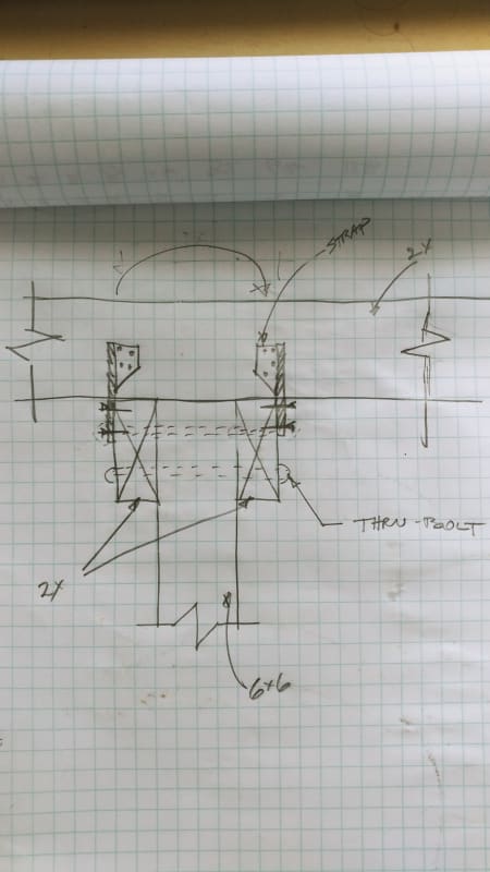
20200715_184506_qtcaoa.jpg
 
Replies continue below

Recommended for you

they're 2x12. unfortunately don't know much about trusses, have not gone to the site yet, but I would assume 2x4 chords and webs. Yes, existing structure is outside in high wind zone. I know for a fact it does not meet local code. Right now, however, the structure itself is exhibiting some degree of racking, and I'd like to be able to pinpoint the cause as improper lateral restraint. At this point I'm going to say that the portal is not designed correctly, and cyclic loading has loosened the straps to the point where they no longer can transfer moment and/or shear.
 
In this sort of situation would the job budget stand for some on-site testing of deflections? Some form of measurements that can be saved would help in the evaluation and to point to places needing reinforcing. Otherwise temporarily attaching some bracing and forcing some racking may do it as a repair guide even if numbers don't work out. A photo or two here may help the experienced to comment usefully.
 
Structee:
That’s a suspect detail for a number of reasons, one of them being that there is a strong likelihood that only one of the 2x beam members will take most of the load from any given truss or group of trusses. This might be due to poor fit-up and drilling of bolt holes, deflection of the trusses due to gravity loads or due to frame action, camber and variable stiffness in the 2x beam members themselves. It isn’t that the detail might not ultimately take some moment, but it will be a racked-up mess if it really has to take much moment. Actually, the light hardware is probably fairly good because it used many smaller connectors. A good thing in designing wood connections. The bolts won’t be in normal bearing across the width of the 6x6 posts, but rather bearing on the low side of the hole, on one side of the 6x6 and on the high side of the hole on the other side of the 6x6, due to single member loading and truss rotation. The combination of loads will not only be almost full gravity load on one 2x beam member, but also the added induced loading from the moment action. They get by with this kinda crap, these kinds of details, because these buildings seldom see the full design load. And, when they do see the max. load, it’s a situation where the designer/builder can claim an extreme, act of God, type of loading, not the designer’s fault. Is this an interior truss bearing, or an exterior post? Why not give some better engineering design info. so people could understand the whole problem, instead of just that detail, sorta?
 
The sloppy bolt holes and the fact the wood will relax under the washers would take this out of the running for me. I bet in about a yr it would rock under small forces. If you can make SDS (GRK) screws work it might be a salable idea to me since it sounds like the forces are quite low. I quite like the moment frame kit noted by Pharm.
 
It will be greatly helpful if you can up load a sketch that shows the truss above. Is it a roof truss? In what manner it racks, excess deflection/rotation?
 
OG and KootK - thank you. I consider myself a blind squirrel in a forest full of nuts, so I tend to get lucky a lot. I do appreciate the comments, though - especially from the two of you.

retired - I have experience in both wood structures and, oddly and specifically enough, a steel mill. If it's common in a steel mill, it's probably best to assume it's not common in a wood structure. Not just the obvious fact that the loading experience by a steel mill every 28 minutes is akin to an act of a very angry God toward a wood structure, wood structures are typically poorly maintained, if at all. Good call on figuring out it's existing - I didn't pick up on that.

Brad - I just noticed in an ad in Structure this month. I don't know if I should be excited or angry - it's a good solution, but what message does it send to architects trying to force us down to less and less wall....

structee said:
Right now, however, the structure itself is exhibiting some degree of racking
You were holding out on us. OG is right - you need to take some measurements. Find the locations where damage has occurred and the connections are starting to separate. While some sort of dynamic testing would be nice, it may not be necessary. For instance, if you can show that the connections are relatively intact away from the posts but have started to pull apart at the posts, you can "experimentally" prove the stiffness distribution to the connections.


This connection has too much slip. It’s no way near a rigid connection between members. I do a bit of carpentry myself. Wood is pretty soft. Holes tend to be a bit sloppy. It takes a while for everything to engage. Significant racking will occur before the load in the fixings catches up.
 
phamENG,

I don't want to sound like I am "promoting" this type of "moment connection", as I've explained, it is only a way of thinking in troubleshooting, not for new design, nor for consideration of acceptance.

By the way, what is the degree of dryness of structural wood for primary structural elements? How it has been handled when design wood connections that require tightness? Just curios.
 
I suggest a 3D analysis. It will be quicker than hand calcs initially, and doubly so once you get to the what-if part. You can put in dummy members to represent connection stiffness/slop for sensitivity analysis. Some assumptions and simplifications will be needed, but the same is the case for hand calcs.

You can also change the analysis to see how far the stiff elements need to move beyond the point where they first hit capacity until the less-stiff elements take up their assumed load, ie what ductility is implicitly assumed.
 
Don't have much to offer over what has been said already. I had an excellent professor in college in my wood design course who made a point to always say you can create a connection in wood that can handle moments but you can rarely actually create a moment connection. Because of wood being non-isotropic and all of the inherent slip with connections be it from sloppy holes, fastener deformation, local expansion/contraction from moisture content change, etc. You usually end up with a cross section/joint rotation that lands much closer to an idealized pin vs rigid.

For the ties you can estimate the stiffness as PL/AE to get a ballpark number just know you'll be missing out on the fastener slip which can end up being significant and as far as I know there isn't any great way to calculate it so need connector manufacturer input. From this you can back into the joint rotation and then compare to the rotation in your analysis model.


My Personal Open Source Structural Applications:

Open Source Structural GitHub Group:
 
retired 13
Your question:"How it has been handled when design wood connections that require tightness? Just curios."
When the truss is made with truss plates, explain how he tightens them.
 
The linked training note is a good reference for bolted connection in wood. Pay attention to p.7 & 8, yielding mode II. Link
 
A good engineer knows the difference between bolted and truss plates. Also known as connector plates.
 
Just learnt there is something about truss plate. I started in the age of wood dowels, keys, that without a single nail, but frames stood no less longer than fastened through modern technics, if not longer.

image_rwdlap.png
 
Two basics to the success in wood works:

1. Select dimensional stable lumbers.
2. Dry the wood properly before installation, for both indoor and out door applications.

Link
 
Reason I ask is each house I have been in they have them, yet I find nothing about tightening them in literature. I'd suspect whacking with a hammer will distort and likely affect their holding power. Perhaps tests have been run by
US Forest products lab has no found problem? So is re-tightening of any connector needed???
 
OG,

Don't you ever retighten the loose door knobs, hinges, drawer handles, and the connection of cheap wood furniture? Nobody will tell you so, but you would out of mechanical instinct. However, if everything is fitted tightly and function properly, why retighten? I broke my car tire bolt by over tightening once, that costed me quite a small fortune, a lesson learnt :)
 
Status
Not open for further replies.

Part and Inventory Search

Sponsor