Eng-Tips is the largest engineering community on the Internet

Intelligent Work Forums for Engineering Professionals

Moment Connection when Minor axis bending is large 8

Status
Not open for further replies.

NewbieInSE

Structural
Dec 19, 2019
234
0
0
BD
Dear Engineers,

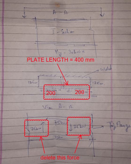
I have got a Beam Splice to design, which has both major and minor Bending Moment (BM). Major BM is 138 kN-m (102 kip-ft), Minor is 30kN-m (22 kip-ft). Please see the snapshot below.

image_odav4l.png


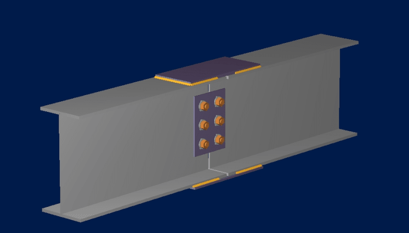
It is taken from RAM Connection Program. The minor BM has been included in the program, but it used only the Major BM.

image_qixtqb.png


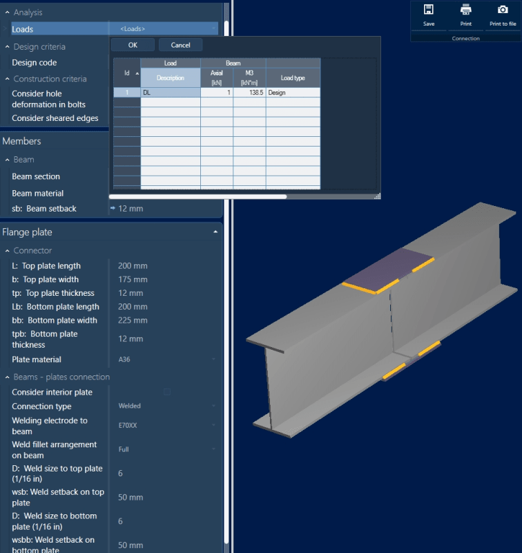
What I want to know is, the weld shown here for Major BM design, will it be adequate for Minor BM too? or Does it require further checks?

Thanks.
 
Replies continue below

Recommended for you

Sammy345 said:
I am talking about forces on weld and you are talking about stiffness.

It's almost as if stiffness and force are directly related by some kind of.. law?

Hookes law --> F=Kx (force = stiffness times displacement). The more your material stretches and the stiffer it is the more force it carries. The flange connection is stiffer k[sub]flange[/sub]>k[sub]web[/sub] and it rotates more (the flange is farther from the N.A. as stated previously), so x is greater for the flange. If k[sub]flange[/sub]>k[sub]web[/sub] and x[sub]flange[/sub]>x[sub]web[/sub] ==> f[sub]flange[/sub]>f[sub]web[/sub]

Hopefully that helps you see how the two are related.

Edit it's possible I misunderstood your original question as well.

Sammy345 said:
n case of simple I Builtup beam we design tge weld between web amd flange for only shear force that is acting on the beam and we never consider tge major axis bending moment force for weld calculation.

You're talking about a built up I-beam made from plates and want to know why there is no moment calculation for the longitudinal weld between the web and flange? I originally thought you were asking why moment wasn't considered in a web connection.
 
Sorry that my response has caused confusion. My post for weld design/check was meant to assist OP (Newbie), but mistaken Sammy as the recipient.
 
I'm curious, do engineers generally consider the difference in strength between longitudinal and transverse fillet welds as shown in Sammy's and retired13's sketches?

Dik
 
dik,

I do consider weld stresses in all three directions, and combine them as vector fields. But I wouldn't reject simplification for certain cases.
 
@Megastructures Right. In case of Built Up I sections we only consider shear .But for OP's connection we are considering major axis momemt as well for weld design .Why?
@retired13 I am still not getting
 
@retired13 If I have simply supported I Beam(Built Up Section) with udl and a concentrated major axis momemt at center.I would still design tge weld between web amd flange for shear force only.But for OP'case why will we check for both major and minor
 
Sammy,

I think you can use minor axis shear, V[sub]y[/sub], to check the weld for the connection plate in OP's case. But it can be misleading, as the minor axis moment causes an localized deflection/curvature on the connection plate, that is to be brought back to be in conformance with the shape of an continuous beam without the cutoff. Note at the gap between beam segments, the effective cross section consists of only the top and bottom connection plates, the beam continuity/rigidity is lost (parallel to Maga's comment).
 
Sammy345 said:
As the minor axis momemt is 30kn-m .It will be divided between the top and bottom flange i.e each flange will resist 15kN-m of load. Thus the force in the flange will be 15/0.2 = 75kN.
Thus force in weld along lengtb 75/200=0.375kN/m
Also i will result in formation of couple like shear .Thus force in weld along width =75/175= 0.428kN/m
Is my understanding correct?

I made the same mistake. The plate length is actually 400mm top and bottom (200 lap to each beam). Force in weld (to each beam) = 75/200 = 0.375kN/m is correct.

There is no "couple like shear" across the beam. The applied moment results in side shear only.

image_rqgzcr.png


BA
 
Sammy,

Wish you can pick out the design forces for the two cases shown below. 1) A cover plate on the beam, and 2) a connection/continue plate on the beam segments.

image_nwavzv.png
 
In the following, I am ignoring the weld across the beam in the top flange. It is probably not a good idea to weld across the beam flange as it may weaken it, so assume only side welds top and bottom.

image_wupwit.png


BA
 
retired13 said:
In this case, the minor axis bending [highlight orange]becomes torsion[/highlight] on the half connection plate, so it is additive to the stress due to major axis bending (Fw = Mx/d), as both resulting in shear in the weld. Note that the shears are to be added together as vectors if they orientate in different direction/axis. Also, do not substract shears in opposite direction, but to use a single weld size for the largest force in the weld lines.

I disagree with the orange highlight. I believe that minor axis bending remains bending in the top and bottom plates.

I agree that shears should be added as vectors, but in this case, I believe the direction is the same.

Subtracting vectors is the same thing as adding but paying attention to sign. It's okay to do that, but I agree that changing weld size would be confusing for the welder and could result in error.


BA
 
BA,

I consider M[sub]w[/sub] is the same as torsion (rotate about the vertical axis), so the weld design f[sub]w[/sub] = M[sub]w*r[/sub]/J[sub]w[/sub].

image_rpqxwa.png
 
retired13,

I don't agree. J is not involved. Torsion for a plate oriented horizontally would be a rotation about a horizontal axis.

M[sub]w[/sub] in your sketch produces bending stresses M[sub]w[/sub]/S[sub]y[/sub] at the middle of the plate (each edge)
where S[sub]y[/sub] = tb[sup]2[/sup]/6, t being thickness and b being width of plate.

BA
 
Think again. You have two tasks here - design the weld and check the plate. I do agree you can simplify the weld design uses F[sub]w[/sub] = M[sub]w[/sub]/b for the longitudinal weld lines. But for this case, the design was already done for the major axis bending use 3 sides weld, so I use equation of torsion to produce more tolerable weld size to add to the existing, rather than over simplification and overly conservative.

For the plate bending stress, yes, f = M[sub]app*[/sub]y/I as usual.
 
retired13,

This is a case of biaxial bending. There is no torsion that I am aware of.
I don't know how to determine the expression [sub]r[/sub]/J[sub]w[/sub] or in fact, what each term means.

BA
 
A side note on how I distinguish moment and torsion in this situation - it is a moment if normal stresses are the concern; and it is a torsion, when shear stress is required.
 
I vote with BARetired, in the original post this was described as strong and weak axis bending, no moment around the member length axis was described or discussed.

This is case of running down a rabbit hole of confusion and sloppy naming. Torsion in this case is NOT a useful concept.

Jim

 
Rotation can occur at any axis. In this case, due to symmetry, we can image half of the plate will be rotate freely due to the internal moment, thus the need of the weld at the end to hold the plate in place. And the weld is subjected to the shear stress produced by torsion.

image_bygvoy.png
 
The connection plate weld design method is the same as the beam web connection with bolted ends. Both subject to torsion as the applied force that would cause separation if without. Hope this makes sense.

image_nmmusa.png
 
Status
Not open for further replies.
Back
Top