Continue to Site

Eng-Tips is the largest engineering community on the Internet

Intelligent Work Forums for Engineering Professionals

  • Congratulations SSS148 on being selected by the Eng-Tips community for having the most helpful posts in the forums last week. Way to Go!

Moment distribution in 3 dimensional

Status
Not open for further replies.

Thunwa

Civil/Environmental
Jan 29, 2020
1
In 2-D, we can distribute moment at any joint by using EI/L of each connected member. So, I tried to distribute moment in 3-D based on 2-D theory but my result did not match the result from RISA-3D. Could you please provided me how to distribute moment in 3 dimensional?
image_xlgq7v.png
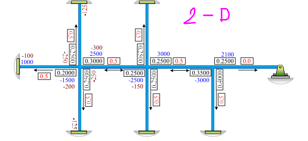
Example for 2-D structure
image_a9xmqm.png
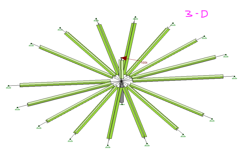
Example for 3-D structure

Thank you all a lot for your help. [bigsmile]
 
Replies continue below

Recommended for you

IMHO, the concept is the same, but much more difficult to visualize in 3D than 2D, thus more difficult to handle and prone to mistakes. There are 16 members in your 3D system, all has the same shape and end supports, thus by inspection, each shares 1/16 of the applied moment (DF = 1/16 each). The direction of the moment in each member is the same as the applied moment, and needs to be subsequently resolved into moment and torsion components about its own axes for design use. The distributed moment is the maximum at the center of the circle, zero at the pin support.
 
I wonder if the moment isn't smart enough to direct itself to the stiffer loadpaths …
normal bending of the aligned members vs torsion in the perpendicular ones ?
torsion reaction on those terminations ??

another day in paradise, or is paradise one day closer ?
 
rb,

It was in my original thought too. But thinking from strain/deformation compatibility of the shared support, distribution seems possible.
 
Wouldn't the distribution be based on torsional stiffness of some of the members (or the combined torsional and bending stiffness, if the members are not orthogonal)? To me, moment distribution seems like an untenable analysis approach for a 3-D structure, especially if you have biaxial reactions.

Rod Smith, P.E., The artist formerly known as HotRod10
 
Thunwa:
It seems that there are many times when the structure is smarter about how it will act, how it must act, than the guys doing the design are smart about how it will act. For simplicity of explanation here, lets assume a 12 beam structure, matching the hour marks on a clock, and that the moment acts in the plane of the 6-12o’clock beams, and about the 3-9 axis. What moment will cause a 1° joint rotation at the center joint on beams 6-12, strictly a fixed end beam bending problem? What moment will cause a 1° torsional rotation on the beams on the 3-9 axis? With the same train of thought, and given their angular orientation from the 6-12 axis, to split bending and torsion components, the beams on the 1-7 and 5-11 axes will be quite stiff in bending, with a small torsional contribution; but the question is the same, what moment causes a 1° rotation at the center joint, resisted by these two sets of beams? That is, M/2 should be applied to each of these beam lines. Finally, the beams on the 2-8 and the 4-10 axes will not be very stiff in bending, most of their moment contribution will be by torsion; but the same question, M/2 for a 1° center joint rotation. Don’t forget to include the moment to 1° rotation calc. for the center column. The relative magnitude of these moments represents the distribution factors for this 3-D problem. Yes, as mentioned above, this moment distribution is really messy. This is an example where some software would be most helpful. Mind you, that the last comment is coming from the guy who has repeated said ‘screw the software and learn to understand how your structure will act, given the way you have detailed it.’
 
Rod,

Good point. I remember ACI do have something for distribution in beam column joint, don't recall the detail though.
 
The 16 members at the bottom all terminate in a pin support, so none of those members can resist torsion. In the particular case illustrated, there is no joint movement, other than axial deformation of the 16 members, which is typically ignored in the moment distribution method. If all members have equal stiffness k, then the total stiffness is ∑k.cosθ where θ is the angle between the applied force and the member. The result will not be exactly the same as Risa-3D because Risa-3D includes axial deformation, but it should be close.

The 2D case shown above is a special case where joint movements are not permitted. When joint movements are permitted, the procedure, even for 2D frames is considerably more complicated, involving further distribution to account for joint movement. For 3D problems, where torsion is to be taken into account, the problem becomes even more complex and is prone to error, rendering moment distribution a possible but rather unattractive method of solving 3D problems.

BA
 
BA,

Agree what you have said. The reason for thinking torsion is because I assume the center support is a fixed joint.
 
In the 3-D structure presented, any way you look at it, you'll have some beams bending and twisting at the same time. Just thinking about how to calculate the effective stiffness of the beam about some odd diagonal axis makes my brain hurt. If you release enough constraints, you can simplify it, but then 1) You've essentially made it a 2-D problem again, and 2) It's analyzing an unbuildable structure, so what would be the point?

Rod Smith, P.E., The artist formerly known as HotRod10
 
Rod,

By my age, my hair color is surprisingly stayed as in my 20s, the secrete is not to waste the brain too much:) I see the beams are drawn identical, thus the properties. So "by inspection" shall be valid here.
 
I think we're reading a lot into a simple sketch.

I'd probably approach the problem from the reactions …

shear … either all react equally, or assume a "sin(theta)" distribution … those members axially loaded are more effective than those carrying the shear in bending. You could "science" this but comparing the bending deflection with the axial deflections

out-of-plane loads … assume a typical bending field (extreme loads at the extreme ends, swapping sign so zero at the "NA")

These two reactions combine to a vector, which'd have components in the member directions.

another day in paradise, or is paradise one day closer ?
 
retired13 said:
I see the beams are drawn identical, thus the properties.

The same beam has a different stiffness for every different axis about which it's bending. Stiffness about the strong axis and stiffness about the orthogonal weak axis are easy enough to calculate, but what about an axis somewhere between the two? To be accurate, torsional stiffness has to be accounted for, as well. Unless those members are all pipes, it gets very complicated to figure out the effective stiffness for even one member. Now, multiply that the number of members at different angles to the direction of loading, and solve the entire system simultaneously. Sounds like a huge headache to me.

Rod Smith, P.E., The artist formerly known as HotRod10
 
Rod,

Maybe I am not that deep. Some member will receive a skewed load, then using member (local) axes resolve it into force components by mechanics. Bending, bending + torsion, torsion, that all the conditions need to be looked at. You can go farther than that for sure, but I wouldn't do it.
 
I already see lots of excellent comments about how this isn't just moment distribution, but in fact is a "2-axis moment plus torsion plus axial" distribution problem.

So instead I'll just add a few RISA model thoughts:
[ul]
[li]One of the first things JoshPlumSE showed me when he was in RISA tech support was to use of the deflected diagram (thanks Josh) when I couldn't understand what my model was doing. Watching the deflected shape has help me numerous times to either understand where I'd messed up my model, or where my thinking was off-base on how the strucure would really work. The obvious key to this is a model that accurately reflects the real structure, or at least your hand calc structure.[/li]
[li]I can't make out how all the members come together at the center. Are they all fixed to the one node, or are there some end releases (BenPin, AllPin, etc.) I can't see? Do these match you hand calc methodology?[/li]
[li]Your load (100 kips) seems huge. Do you have p-delta turned on? This would radically change the RISA results compared to a hand calculation that ignores p-delta.[/li]
[li]The 100 kips load doesn't seem to align with either a member, or halfway between two members, which would be tough in a hand calc. This may be an optical illusion in the screenshot.[/li]
[li]You're using custom member properties rather than standard wide flanges or channels for your radial rafters. Seems odd, but perhaps these are "unit" shapes to make the hand calcs easier.[/li]
[li]From the screenshot the radial members aren't equally spaced (makes the hand calc more difficult), or perhaps a couple of them are turned off.[/li]
[/ul]

Good luck.
 
retired13 said:
You can go farther than that for sure, but I wouldn't do it.

My point is that I don't believe you'll have an accurate analysis if you don't include the complexities necessary to get you an accurate estimation of the stiffness of the members about their actual bending axis. That is why I don't believe moment distribution is a good option for analyzing a 3-D structure, especially one as complex as the one shown.

Rod Smith, P.E., The artist formerly known as HotRod10
 
Status
Not open for further replies.

Part and Inventory Search

Sponsor