sticksandtriangles
Structural
I am looking for some guidance on the FEM design of high seismic moment frame baseplates.
A little background:
Design criteria, fixed base column:
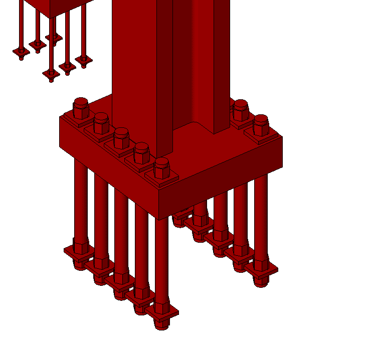
I have sized up an unstiffened baseplate... 9" thick grade 32 steel baseplate (massive!!). Uses (5) 3 1/4"Ø grade 105 anchor bolts. This is based on a purely rigid BP assumption and based on DG#1 examples.

I want to explore what the thickness of the baseplate needs to be using a stiffened design and do a little FEM modelling to confirm the software rigid BP assumptions.
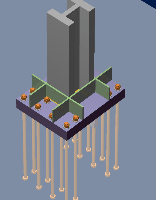
Using RAM connections stiffened baseplate design module, it looks like a 7 1/2" thick baseplate can get the job done.

Ideally I would like to get into the 5"-6" range of BP thickness with stiffeners as required and have started to dive into a little FEM modelling to see if I can not get into this range.
FEM Model Development:
I have developed a SAP2000 model with compression only elements (gap elements) for the grout bearing, tension only elements (hooks) at the anchor bolt positions and modelled the baseplate as a non-linear shell. This is my first hurrah into heavy non-linear modelling so I am somewhat intimated by trying interrupt my results. I have started with the unstiffened design to get a feel for the more simple approach.
Questions I have:
[ul]
[li]How do i accurately model the stiffness of the grout bed/concrete foundation below?
[ul]
[li]Anchor bolt stiffness?[/li]
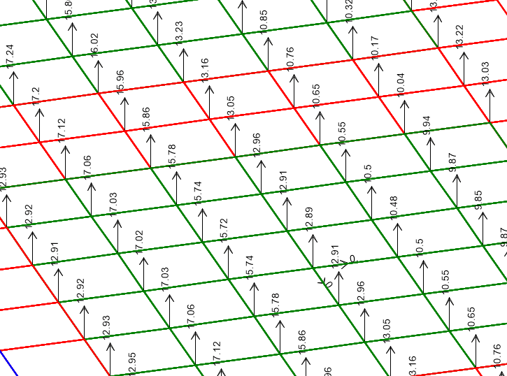
Image of high concrete compressive stress (each square is 1"x1"):

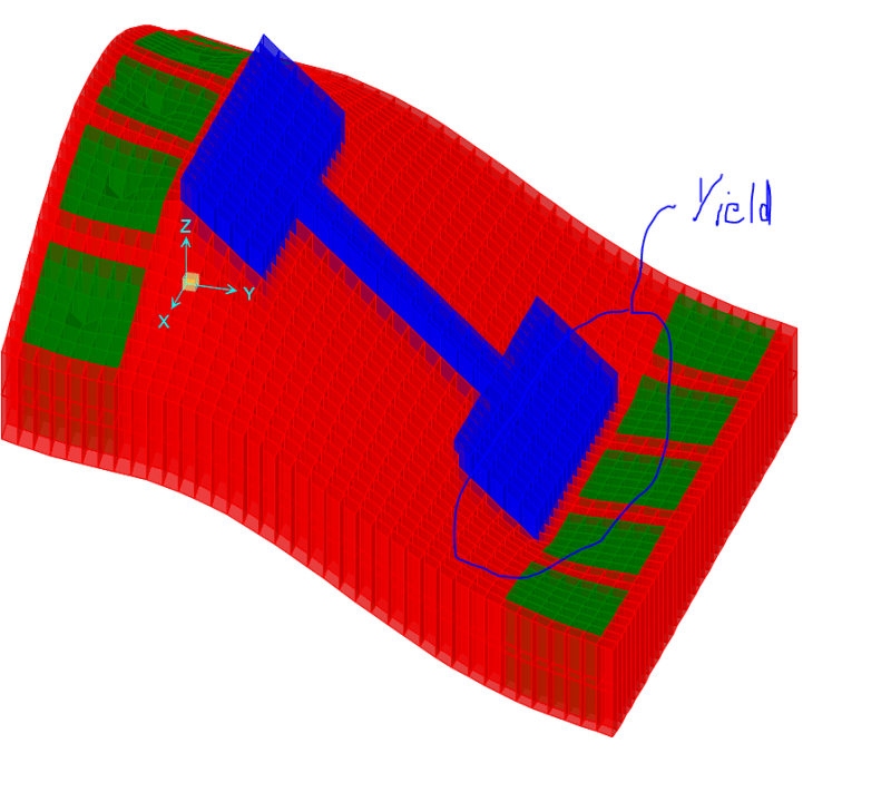
Images of the SAP model for reference under Axial and Moment Load listed above (shows signs of local yielding at edge of flange):

Thanks!
S&T
A little background:
Design criteria, fixed base column:
Column = W14x730
Moment = 2200kip*ft, Omega Moment = 6600 kip*ft
Axial = 140 kips (T) Omega Axial = 420kip (T)
I have sized up an unstiffened baseplate... 9" thick grade 32 steel baseplate (massive!!). Uses (5) 3 1/4"Ø grade 105 anchor bolts. This is based on a purely rigid BP assumption and based on DG#1 examples.

I want to explore what the thickness of the baseplate needs to be using a stiffened design and do a little FEM modelling to confirm the software rigid BP assumptions.
Using RAM connections stiffened baseplate design module, it looks like a 7 1/2" thick baseplate can get the job done.

Ideally I would like to get into the 5"-6" range of BP thickness with stiffeners as required and have started to dive into a little FEM modelling to see if I can not get into this range.
FEM Model Development:
I have developed a SAP2000 model with compression only elements (gap elements) for the grout bearing, tension only elements (hooks) at the anchor bolt positions and modelled the baseplate as a non-linear shell. This is my first hurrah into heavy non-linear modelling so I am somewhat intimated by trying interrupt my results. I have started with the unstiffened design to get a feel for the more simple approach.
Questions I have:
[ul]
[li]How do i accurately model the stiffness of the grout bed/concrete foundation below?
My thoughts, E of concrete is readily defined, but what do I assume for deflection? What I did in my model was take E*trib area/deflection = stiffness (utilized 8600 kip/in for a 1 square inch finite element)
[/li]Utilizing this approach with a linear compression element yields very high concrete stresses. I have stresses in the range of 13ksi. my allowable for 5ksi concrete is around 5.5ksi
I was thinking maybe I could model some non-linearity into the compression only element to allow for stress resdistrubtion within the bearing area to limit stress to the 5.5ksi range, but I am not sure if that is truly how the grout bed below would behave. I would assume that it locally crushes and fails? My DG#1 original design utilizes a rectangular bearing strength assumption though so I feel ok with this.
[/ul][ul]
[li]Anchor bolt stiffness?[/li]
I did A*E/L for the anchor bolts. Yields a stiffness of 8020 kip/in. I have a long embedment of 60" on these 3 1/4"Ø ABs
[/ul]Image of high concrete compressive stress (each square is 1"x1"):

Images of the SAP model for reference under Axial and Moment Load listed above (shows signs of local yielding at edge of flange):

Thanks!
S&T
