Continue to Site

Eng-Tips is the largest engineering community on the Internet

Intelligent Work Forums for Engineering Professionals

  • Congratulations KootK on being selected by the Eng-Tips community for having the most helpful posts in the forums last week. Way to Go!

Moment required to prevent (free) falling object from rotating 1

Status
Not open for further replies.

Gios

Mechanical
Jan 27, 2022
3
Hello,

I am new to the forums so I hope I am posting this in the correct forum.
I will try to explain the problem below:

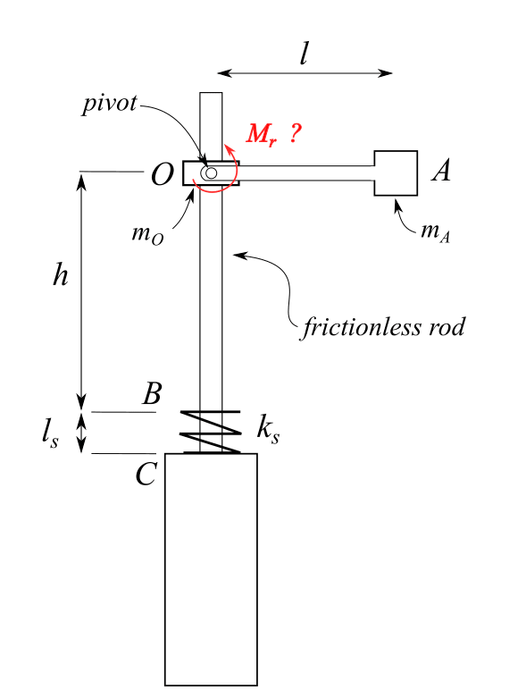
Link OA can pivot around O without friction.
Mass m[sub]O[/sub] is left to free fall for height h guided by the frictionless rod until it hits spring k[sub]s[/sub].
Spring k[sub]s[/sub] then deforms and any downward motion stops when it deforms completely (l[sub]s[/sub]).

What would be the required moment M[sub]r[/sub] to prevent link OA from rotating when the motion stops?

What would be the best srategy to solve this problem?

Thank you!
engineering-forums-question_xrove1.png
 
Obviously, W × L, where W is downward force, and L is distance from the pivot to the center of mass of the rotating link.

In a static situation, W is simply weight of the link.
In a dynamic situation where the mechanism slams down on the spring, your downward force is is weight plus mass × deceleration because inertia will tend to carry your link down further and you need to counteract that tendency with your moment Mr.
 
Hi Gios

I need to understand more about what you are trying to do with this device so I have the following questions

1/ what position is the link O - A in before the mass Mo falls ?

2/ If it’s in the horizontal position as shown in the sketch, then what holds the arm in this
position when Mo is falling?

3/ Which way does the arm O-A rotate when Mo hits the spring and stops?


“Do not worry about your problems with mathematics, I assure you mine are far greater.” Albert Einstein


Scuka said:
Obviously, W × L, where W is downward force, and L is distance from the pivot to the center of mass of the rotating link.

In a static situation, W is simply weight of the link.
In a dynamic situation where the mechanism slams down on the spring, your downward force is is weight plus mass × deceleration because inertia will tend to carry your link down further and you need to counteract that tendency with your moment Mr.
Hi Scuka, thank you for replying.
The approach makes sense. The dynamic factor is what I am trying to determine.
I think conservation of energy + conservation of momentum would be a good staring point.


desertfox said:
1/ what position is the link O - A in before the mass Mo falls ?

2/ If it’s in the horizontal position as shown in the sketch, then what holds the arm in this
position when Mo is falling?

3/ Which way does the arm O-A rotate when Mo hits the spring and stops?

Hi desertfox, thank you for the reply.
To answer the questions:
1/ It is in the horizontal position

2/ There is a moment applied (like M[sub]r[/sub]) which for the static case it is straightforward. For the dynamic case though we would have to calculate the peak moment which is required to prevent the arm O-A from rotating downwards when stopping.

3/ It would rotate downwards (due to momentum from free fall) and that is what I would like to prevent by calculating the required moment.

 
Use work and energy during the free fall to find the velocity when m(o) contacts the spring.
Then find the distance and time to compress the spring to determine the resulting moment created by the spring force acting to stop the fall as the spring absorbs the kinetic energy.

Ted
 
hi Gios

Why not just rigidly pin the arm or fasten it to the mass Mo in the horizontal position? Why is the arm O-A free to rotate in the first place?

“Do not worry about your problems with mathematics, I assure you mine are far greater.” Albert Einstein
 
is this for work or school ?

another day in paradise, or is paradise one day closer ?
 
desertfox, just a guess but probably wants to know the reaction on the frictionless shaft.

Add an overhanging mass directly opposite to create an equal and opposite moment.

Ted
 
If there is no rotation allowed then the torsion spring required will be infinitely stiff. What you can calculate is the amount of torque that will be applied if the spring is infinitely stiff - that is, if the arm is completely rigid and the connection is completely rigid and the vertical rod is completely rigid.

The total potential energy will tell what the compression force in the spring will be and that force times the weight on the arm times the length of the arm, less the force to accelerate the mass confined on the rod, will be the torque.

F = (m1+m2)*a; T = m2*L*a.
 
Looks like a student post to me. No one draws diagrams that nice at work.
 
I'm wondering if it's a trick question? "when the motion stops" ... so the moment is (when the motion has stopped) ma*g*L

another day in paradise, or is paradise one day closer ?
 
rb1957 said:
is this for work or school ?

This was based on a discussion we had with colleagues. The situation without the rotating arm is straightforward but the arm makes things a bit more complex.
No one could give a credible answer about calculating the moment.

desertfox said:
Why not just rigidly pin the arm or fasten it to the mass Mo in the horizontal position? Why is the arm O-A free to rotate in the first place?
Hi desertfox.
Well we were discussing about having a rotating arm and fastening it at point O in order to prevent rotation. Some people suggested fastening as much as possible but I would also like to calculate the required moment.

3DDave said:
If there is no rotation allowed then the torsion spring required will be infinitely stiff. What you can calculate is the amount of torque that will be applied if the spring is infinitely stiff - that is, if the arm is completely rigid and the connection is completely rigid and the vertical rod is completely rigid.

The total potential energy will tell what the compression force in the spring will be and that force times the weight on the arm times the length of the arm, less the force to accelerate the mass confined on the rod, will be the torque.

F = (m1+m2)*a; T = m2*L*a.
This is interesting, I will try to work on this

hydtools said:
Use work and energy during the free fall to find the velocity when m(o) contacts the spring.
Then find the distance and time to compress the spring to determine the resulting moment created by the spring force acting to stop the fall as the spring absorbs the kinetic energy.


Makes sense. I was thinking work- energy theorem until the moment before impact onto the spring and then again until the spring is compressed completely ( downwards v=0).
This would give me the peak force on m[sub]O[/sub] at that moment. Can this also be used for m[sub]A[/sub] though?

SwinnyGG said:
Looks like a student post to me. No one draws diagrams that nice at work.
No student post, I just haven't used Inkscape for quite a long time and wanted to work with it a bit [smile]


rb1957 said:
I'm wondering if it's a trick question? "when the motion stops" ... so the moment is (when the motion has stopped) ma*g*L
No trick question, by "motion stops" I meant v=0 at max compression of the spring (x=l[sub]s[/sub]). Sorrr if it wasn't clear
 
The wording around "prevent rotation when the motion stops" is a bit hard to follow but, if you want the link to remain perpendicular to the guide rod throughout the evolution, then it might be less confusing to reframe the problem in terms of a rigid connection and a desire to calculate the peak bending moment at the root of the link. Exactly the same problem, with exactly the same approach to solution already proposed by various other posters - but maybe a useful intermediate step to accepting the validity of the solution.

A.
 
Gios:
Actually, a real “conservation of energy” would have most of us ignoring these kinds of silly questions/problems, and spending our time working for the guy (or company) who is actually paying us. These kinds of questions should be asked of their T.A. or Prof., so the whole class can benefit from the discussion, or contemplated privately, and near a test stand, and then turned into a Ph.D. thesis.
 
Gios, draw a free body diagram at the moment of spring contact. Spring force acting at m(o), reaction moment of the rod and m(o), combined weights of both masses. Spring deflection to absorb k.e. will give max. spring force.

Ted
 
It isn't as simple as that if you ignore friction and damping. As the masses drop at g nothing very interesting happens. When mo strikes the spring at B, the ma continues to accelerate down, but at less than g, and swings on the arm. Assuming the spring/mass system has a higher frequency than the pendulum system, mo rebounds and starts to move up as ma continues to swing, and also starts to move up, perhaps. Then it gets really complicated.

Cheers

Greg Locock


New here? Try reading these, they might help FAQ731-376
 
You guys are way overcomplicating.

Imagine that the pivot where A mounts to O does not exist, and they are rigidly fixed together.

OP is asking what the bending moment in the link between O and A will be at the bottom of travel.

In order to know that, OP, you need to know the force the spring will apply, i.e. you need to know the spring rate. This should be obvious; the softer the spring is, the softer the O/A member will land. Less peak force means less peak moment in the member.

-Calculate KE at the moment O and the spring come into contact

-Use the KE of the system to calculate the deflection in the spring at the moment O is stationary

-Use the deflection in the spring to calculate max spring force

-Use the max spring force to calculate the max bending moment in the member


I guess I made it complicated with of course assumptions.[smile]

Total potential energy of link OA = (m[sub]0[/sub]+m[sub]A[/sub])*g*(h+l[sub]s[/sub])
Total Kinetic energy of link OA before the velocity becomes zero at point B = (1/2)*(m[sub]0[/sub]+m[sub]A[/sub])*v[sup]2[/sup]
Total energy stored in spring once link compresses the spring = (1/2)*k[sub]s[/sub]*l[sub]s[/sub][sup]2[/sup]

Assuming the total potential energy is not converted to spring elastic energy (may be spring is not compressed full or even with full compression some amount of energy is remaining) but remaining energy is converted to rotational energy of link OA, then-

Rotational energy of link OA = Total potential energy of link OA -Spring elastic energy
(I*α*θ) = (m[sub]0[/sub]+m[sub]A[/sub])*g*(h+l[sub]s[/sub]) - (1/2)*k[sub]s[/sub]*l[sub]s[/sub][sup]2[/sup]
Total anti-torque required at O to prevent this rotation T=I*α

so Moment/Torque = I*α = [(m[sub]0[/sub]+m[sub]A[/sub])*g*(h+l[sub]s[/sub]) - (1/2)*k[sub]s[/sub]*l[sub]s[/sub][sup]2[/sup]]/ θ.

Another assumption- the moment M = m[sub]A[/sub]*g*l is required to be applied at O to maintain the static equilibrium throughout time.

So effectively total moment/torque required to keep link OA horizontal= static moment(m[sub]A[/sub]*g*l) +dynamic moment(I*α)

Where I = m[sub]A[/sub]*l[sup]2[/sup] = mass moment of inertia of mass m[sub]A[/sub] about O.
 

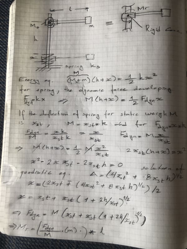
I did not read the previous posts in detail and hope my post will not be repeat of the one of them . If the rod OA has hinge connection and can pivot around O without friction and if we are looking for the resisting moment Mr to prevent rod OA from rotating when the motion stops, it is literally means, to locate a RIGID TORSION SPRING at O and look for the moment developing at the torsion spring. That is, literally rigid conn. of the rod to the pt. O.

If we assume frictionless rod and the impact is fully elastic, the approach would be with conservation of energy .Pls look to the following hand calculation .

IMG_impact_0195_czky7o.jpg


PS. this is the third attempt to send my post since today morning .. could be internet conn. problem .
 
Status
Not open for further replies.

Part and Inventory Search

Sponsor