Continue to Site

Eng-Tips is the largest engineering community on the Internet

Intelligent Work Forums for Engineering Professionals

  • Congratulations KootK on being selected by the Eng-Tips community for having the most helpful posts in the forums last week. Way to Go!

Moment Resistance of Single Angle

EngDM

Structural
Aug 10, 2021
389
Hey all,

For a typical loose lintel angle being used to support a new opening in masonry, what do you typically take as the moment resistance? I've done some sanity checks in RISA and they appear to take it about the principal axis, and proportion the moment into both the local axis's to then use the Mfx/Mrx + Mfy/Mry equation. I'm wondering if it would make more sense to use the properties about the geometric axis for my use case, considering the angle will be pinned down by the block wall and can't rotate to actually be loaded thru the principal axis, as well as being anchored to the block wall thru the vertical leg which would provide even more rotation resistance. I'm stuck at a 3/8" thick angle to fit in the grout space, and I need quite a long vertical leg if I use the combination equation that is done by RISA.
 
Replies continue below

Recommended for you

In our office we use the old British code method of checking the angles in that case. BS5950 I think.
 
It doesn't matter if it can rotate or not - you can check moment as flexure about the geometric axis or split it into moment about both principal axes, though the former is much simpler. I don't know if CA means canada or california. S16 does not have formulas for angle bending about the geometric axis, but AISC 360 does.
 
I typically only check deflections on these using Ix. That seems to control for lintels assuming you use more than L/600 and account for arching etc.
 
I typically only check deflections on these using Ix. That seems to control for lintels assuming you use more than L/600 and account for arching etc.
Agree with this.
 
I do the same as XR & Jayrod for loose brick lintels.

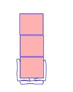
Is this actually a new CMU opening where you'll have angles on both sides of the wall? If so, I usually do that with patch plates on the bottom which would tend to prevent rotation as you suggest.

c01.JPG
 
It doesn't matter if it can rotate or not - you can check moment as flexure about the geometric axis or split it into moment about both principal axes, though the former is much simpler. I don't know if CA means canada or california. S16 does not have formulas for angle bending about the geometric axis, but AISC 360 does.
CA = CAN, should really be clarified site-wide.

I took a look at AISC 360 and it seems my Mr should be phi*Mn = 1.5*My with the Fy reduced in accordance with slenderness/local leg buckling.
 
I do the same as XR & Jayrod for loose brick lintels.

Is this actually a new CMU opening where you'll have angles on both sides of the wall? If so, I usually do that with patch plates on the bottom which would tend to prevent rotation as you suggest.

View attachment 942
Angle will only be on one face.
 
for a loose lintel I believe you'd fall into the category of being "without continuous lateral-torsional restraint" which would kick you to principal axis design in AISC.

AISC F10:
Single angles without continuous lateral-torsional restraint along the length shall be designed using the provisions for principal axis bending except where the provision for bending about a geometric axis is permitted.

If the moment resultant has components about both principal axes, with or without axial load, or the moment is about one principal axis and there is axial load, the combined stress ratio shall be determined using the provisions of Section H2.
 
Angle will only be on one face.

Yuck. No access to the other side?

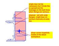
That will be a fair bit of eccentricity and, therefore, perhaps warrants more serious checking. To that end, keep in mind that your worst condition for torsion etc will be the bearings at the ends. Our design provisions kind of assume torsional restraint that mobilizes the entire cross section. That's rarely the case and will be very far from the case here.

Another option shown below.

I favor robust conceptual choices over fancy equations, always.

c01.JPG
 
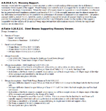
FYI, the OBC has perscriptive lintels in part 9 (Table 9.20.5.2(2) ). The current NBCC just has it for veneers, but the OBC has it for supporting floor loads as well. I think this is an OBC addition and not a thing that used to be in the code and is just still in the OBC because it's so old compared to the current NBCC. Not 100% though. I'd drop the PDF in but the OBC pdf is weird.

The notes for the veneer ones have a design basis. (attached)


Attachments

  • lintel design basis.png
    lintel design basis.png
    170.8 KB · Views: 9
for a loose lintel I believe you'd fall into the category of being "without continuous lateral-torsional restraint" which would kick you to principal axis design in AISC.

AISC F10:
If I am anchored to the block I am supporting along its length then I am torsionally restrained no?

Also after further inspection it's not a bearing wall, just supports some infill block.
 
Yuck. No access to the other side?

That will be a fair bit of eccentricity and, therefore, perhaps warrants more serious checking. To that end, keep in mind that your worst condition for torsion etc will be the bearings at the ends. Our design provisions kind of assume torsional restraint that mobilizes the entire cross section. That's rarely the case and will be very far from the case here.

Another option shown below.

I favor robust conceptual choices over fancy equations, always.

View attachment 946
Angle is flipped so that the block bears on the horizontal leg, and the block grout is removed to slot the angle into the wall at each end, 8-16" of bearing typically.
 
That shear center is definitely inside the block somewhere, without question, for channel it’s outside the shape to the right (e naught in the manual?), as KootK drew it, the shear center of the angle is at the “pole” where the legs intersect and the plate is in the mid-line of the plate, so however you connect it, the shear center for the composite shape is outbound of the channel web to the right. Unless you want to go all pathological with a zero width channel web or some other picky picky nonsense.

Having just dealt with this for a 1940s era structure where they most likely didn’t consider torsion, (which the contractor then destroyed…)

For modest spans you can make some fairly conservative steps to simplify the analysis and still get a normal section to work, and arching action is another mitigating possibility to consider. Personally it seems the brick can restrain at least some of the left-right moment induced by a single angle, though I don’t see many folks using that in their analysis.

Technically a solo single angle goes into biaxial bending when loaded like this, and torsion. So if you do a simplified analysis, keep the stress level below 100% of the allowed.
 

Part and Inventory Search

Sponsor