Eng-Tips is the largest engineering community on the Internet

Intelligent Work Forums for Engineering Professionals

  • Congratulations waross on being selected by the Tek-Tips community for having the most helpful posts in the forums last week. Way to Go!

Momentary open-circuit issues in brushes/slipring contact 8

Status
Not open for further replies.

Shahriar Kamrani

Mechanical
Nov 8, 2018
9
0
0
GB
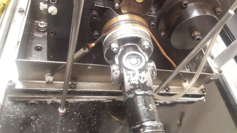
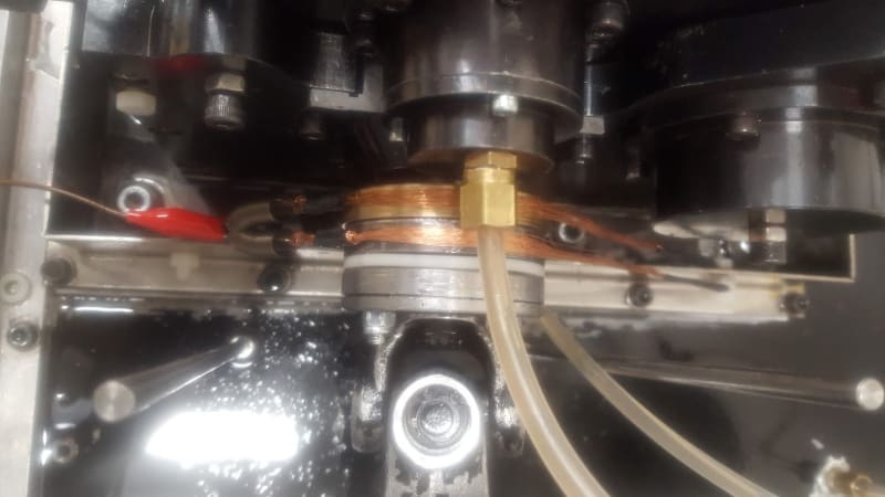
I have two phosphor bronze PB1 sliprings of 60 mm in diameter and 10 mm in thickness and two brushes of carbon graphite with 8 mm in thickness. I am interested in applying a voltage from one of the slipring/brushes contacts, through the shaft (and load) and then collect it from the other slipring/brushes. As I am interested in monitoring this "contact" voltage at high frequency for data acquisition purposes, I have realised that I have an open-circuit at every 1-10 points per slipring cycle.
I have tried multiple different approaches to eliminate this by using different brush spring force, slipring material and conductive grease for the brushes/slipring, with no success. I think one problem that might also influence this is the oil/lubricant vapour reaching the surfaces of the slipring/brushes and act as a dielectric material.
Is there any suggestions/tips of how I can improve the slipring/brushes contact and also keep the lubricant away from the surfaces?

Thanks,
 
 https://files.engineering.com/getfile.aspx?folder=7fb9b56a-989d-460b-83d2-e6927ce3fa64&file=20180228_142753.jpg
Replies continue below

Recommended for you

Please check in with us in a few weeks and let us know your results.
Thanks.

Bill
--------------------
"Why not the best?"
Jimmy Carter
 
Just an afterthought to the discussion.

The term "brush" typically implies some form of item with multiple [bristles] or tentacles.
Early versions of motor brushes were indeed just like what most would interpret today as a paint brush, or a scrub brush and so on.
They were a Brush.

A trip to an industrial oriented museum exhibiting first generation era dynamos with original
brushes on the machines will visually confirm for those curious about what brushes originally looked like.
It also lends to authenticate how the term may have been originally coined.
They were a Brush.

Those involved in 21st century problems related to electric motors are likely familiar with "grounding brushes".
The concept of their design has been borrowed from or reverted back to the original premise of multiple bristles/tentacles
to make continuous contact with a revolving member.

An Aegis product comes to mind only because I've installed them around motor shafts.
It's an item with very small multiple tentacles or connection points. It's a brush surrounding a shaft.

I don't know anything about the science behind the product... "but" one can guess or assume that
somehow each end of the individual bristles (as they are sacrificed during their embrace with potential),
that their severed connections are replaced by adjacently connecting bristles until eventual failure.

I'm thinking... You need more contact points!

Purely a guess... on a Friday night ; )

John
 
I have one Mercotac. Salvaged when environment people found that they contain Mercury. As its name implies. Seems to be against several laws to use them today.

Re the AEGIS from ETS (Electron Transport Systems): one of their probes (not a complete ring, just a sector), is easier to apply. You just touch the slip ring with it. The complete rings need special arrangements and some attention to actual diameter of shaft or slip ring.

Gunnar Englund
--------------------------------------
Half full - Half empty? I don't mind. It's what in it that counts.
 
For digital, how about a LED on the axis of the shaft and a fixed photo diode receiver. The rotating circuit can be powered thru a rotary transformer.
 
Update:
As @Skogsgurra suggested, I have wires to see if that make any difference in terms of improving the electrical circuit and it seems that the wires improve the electrical circuit significantly and I no longer see those open-circuit moments.
I will look into a permanent solution so I can have both brushes and the wire brushes (KC attachment method), so I can assure a good connectivity - will post another update when this is ready.

@Skogsgurra - you mentioned that stranded steel wires are a good choice, however, I am thinking of using KC attachment method on the steel disc while keeping the brushes (bronze blocks) on the slipring. Hence, as I should avoid using similar materials, do you suggest using copper wires for the steel disc (black disc next to the bronze slipring).
 
 https://files.engineering.com/getfile.aspx?folder=eddc84c2-2c97-48fd-b4db-09907cd87c6e&file=20181115_200726.jpg
The signal is not strong enough to survive the interface between the slip rings and the carbon brushes.
This is for testing. I understand that the OP is willing to sacrifice longevity for signal integrity.
Yours Bill

Bill
--------------------
"Why not the best?"
Jimmy Carter
 
Update:

I have used a setup similar to the one proposed by Gunnar and it worked quite nicely. I have used copper wires to make a rope with two sides wrapped in a circle to make a hook. One side is attached using nylon washer and bolt to the base (isolated) and the other side attached to a spring and the spring attached to the base (with nylon washers, bolt, and nut). I have used the setup for a few days and the wear rate was quite minimal with no momentary open circuits. However, due to high oil temperature, the ropes get dirty quite fast (oil mist and vapours) and need replacement at the end of each test. But overall a good solution.

I am planning to run a long test within the next 2-3 weeks and will update you on this.

20181212_195416_cdxdfb.jpg

20190214_124210_tcynfn.jpg
 
Impressive solution. Can visualize bringing the wrap further around the slip rings would create additional surface contact if desired.

Thank you for the posted update.

John
 
You could use oil free air running out of a small little oil-less air compressor as a purge around the wire contacts to keep oil air at bay.

Also

From your original drawing with the '10Ω grease resistor' I can't understand why, if you're measuring current, the 60k resistor wouldn't be vastly superior to the 10Ω one. The signal for you to measure should be 6,000 times better.

Keith Cress
kcress -
 
@dArsonval - my pleasure, will hopefully update this again soon.
@itsmoked - Thanks for the reply; could you please clarify (maybe using a link or sketch) how I can implement the oil-less air compressor close to the brushes? I have initially used 10Ω current-measuring resistor with a 100kΩ resistor (thought this was appropriate but then change this resistor to a lower value) as I read the shunt resistor should be less than thousands of times of the load? And since then I maintained my shunt resistor as this value, as my 'load' didn't change, giving me at least a ratio of 2000 (20kΩ/10Ω).
 
Status
Not open for further replies.
Back
Top