Continue to Site

Eng-Tips is the largest engineering community on the Internet

Intelligent Work Forums for Engineering Professionals

  • Congratulations SSS148 on being selected by the Eng-Tips community for having the most helpful posts in the forums last week. Way to Go!

Monumental Stair Vibration 2

Status
Not open for further replies.

T_Bat

Structural
Jan 9, 2017
213
Hey everyone,

I'm looking at a monumental stair design. The stair spans about 33' measured on the flat and has a rise of 18' total. It's one span with no opportunity for posts and is about 7' wide. I've got some relatively large HSS stringers on each end (HSS16x4). The pans will be at least 3/16" thick and will have closed risers. Strength and deflection aren't really an issue - but I'm concerned about vibrations. I used the simplified models from the new AISC DG11 for stairs but they are requiring some very large stringers.

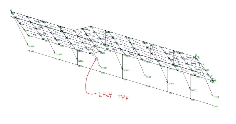
I'm trying to capture the actual (or reasonably close) frequencies for this in RISA. Short of modelling every pan, I've done the following:

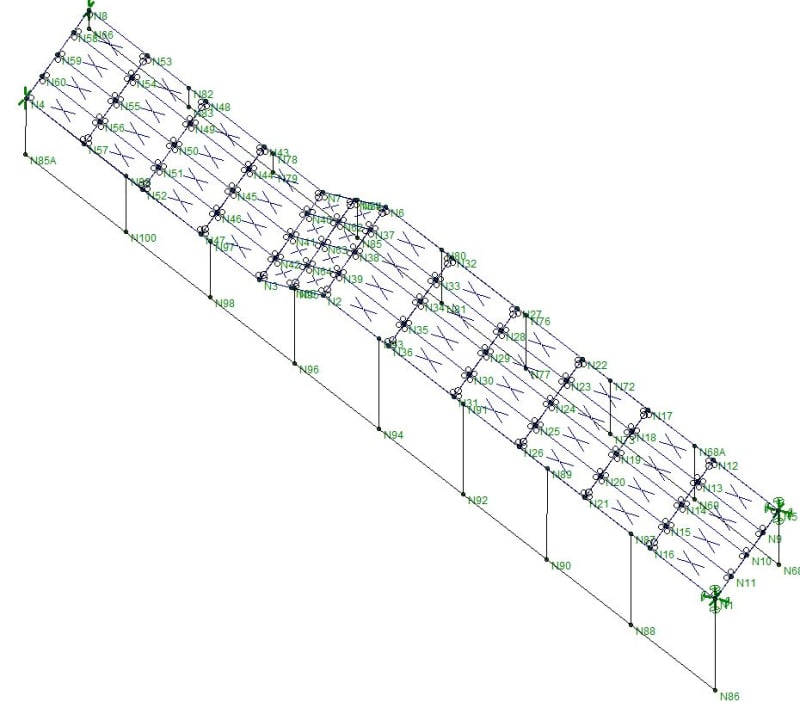
1. I've modeled flat plates between the stringers to capture the deep beam action for horizontal sway.
2. I've modeled small L3x3 angles between the stringers at intermittent locations matching the plate nodes. I can run the model without these but I get a lot of local mode shapes for the plates themselves. I consider these extraneous to what I'm doing. The angles modeled basically eliminate these modes and I feel this is reasonably accurate because I'll have a closed riser and pan assembly that creates an angle anyways. Although my modeled angles aren't as often as I'd have risers.
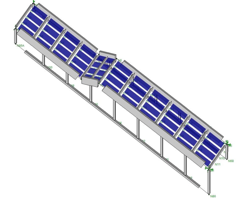
3. As a design note, there are HSS tubes hanging from the stringers to carry a wall. I've modeled these because I feel, if detailed properly, these will help stiffen the stringer for vertical movement - think some vierendeel truss action.

The first mode shape appears to be lateral movement of the wall hanging assembly and corresponds to 4.54 Hz. I can probably eliminate this mode since there is cross-bracing between the wall assemblies that I haven't modeled. The second mode shape is vertical movement of the entire stair assembly at 4.93 Hz. I've run to 20 modes just to see what all is happening. In those 20 there isn't a dominant "horizontal" shape, which makes sense to me since, the plates effectively tie this thing together to act like a deep beam horizontally.

Anything I'm missing here that would cause me to overestimate the frequencies?

Capture_jnxar2.jpg

Capture2_oqrk5s.jpg
 
Replies continue below

Recommended for you

You could put some diagonals in the hanging wall to significantly stiffen up the structure if needed at the expense of making the wall framing more difficult to install.
Also, make sure you check the flanges of the tube moment connections as they want to bow inward or outward.
 
The "flexibility" of your top and bottom support will affect the behavior. You will want to consider how rigid your diaphragam/foundation and vertical load carrying members are. As a starting point you can utilize vertical and horizontal springs to help get a feel for how it might affect behavior.

 
Since frequencies depend on stiffness and mass, one would try and capture both as much as possible (one could use say consistent mass matrix on beam elements to capture the mass better, add non-structural mass , crowd and other things that add mass....).

Not sure how the mesh is like, but typically in dynamics one would use a few beam elements per member depending on the mode shape one wants to capture (typically 3-8 elements per wave-length).

Another thing in dynamics (and statics very likely), is that it is very seldom that FEA and real structures agree (natural frequencies), and most often one needs to tune the FEA model to get closer to reality (experimental modal measurements). See: Link
In any case if this is not possible, a statistic approach could be taken.

Damping is an unknown (unless measured), but if one assumes it is low it does then not have much influence on frequencies (mainly forced displacement/amplitudes).
At last, BC can have an impact as well, so capturing that correctly is important as well (one can add a static stiffness, but that is not always the same as the dynamic stiffness of a connection).
Again tuning models in is common for adjusting the stiffness at these locations.

As for the plates local modes, they will typically have higher frequencies (depending on their size to weight and stiffness) than global modes, but they could be important since they add mass (and perhaps some stiffness) to the structure that will thus influence the global modes as well.

Hope this helps.


I never worked with RISA so I really don't know if the circles at the ends of the members represent pinned connections. If they do, you could change this to full continuity between members. Since the amplitude of the expected movement for vibration in service conditions (typically a DL+0.10*LL load) is very small, it's common practice to assume continuous members throughout the structure.

Besides AISC DG11, there's additional guidance in SCI publication 354 "Design of floors for vibration: A new approach", which can be obtained for free here.

The Concrete Centre's guide "A Design Guide for Footfall Induced Vibration of Structures" (developed with ARUP, if I'm not mistaked), is also a great source of guidance. This one can be bought here.
 
The stair attaches to two concrete slabs that are 12" thick - they would be welded to embed plates. I've modeled the stair as pin-roller so obviously there would be some fixity that I'm not accounting for. However, for my purposes that would make my current boundary conditions conservative, right? I'll mess around with vertical springs to see what happens there.

XR250 - there will be some diagonals for the wall hanging assembly. I went ahead and modeled them and, as suspected, they eliminate my first mode described above.
 
I think XR was indicating if you added vertical bracing in the HSS hanging wall it would stiffen the vertical movement such that it may eliminate or at least reduce the likelihood of that mode governing as well.
 
Ah gotya - sorry for the misunderstanding. I'd really like to avoid that if possible. It will be infilled with studs. I'm fine with the design I have (although I may tweak the stringer size after some more investigation). I'm more concerned with my analysis and whether it reasonably captures the behavior of the stair from a conceptual standpoint.

Is there a better way to look at this? For example - is the pan simplification to plates a reasonable assumption? Does adding the angles to eliminate the extraneous plate element modes make sense? Is there a better way to accurately look at this?
 
Model with braces for clarity...
Capture3_zsjpuy.jpg
 
What were the results of the DG11 calculations?

Are you sure the sizes are unreasonably large? DG11 Example 4.6 is roughly similar to yours, and they're showing HSS20x12 stringers.
 
Those sizes are unreasonably large for my stair. The fabricator is not prepared for something that large and the architect has sized everything based on a 4" wide stringer. If possible I like to fit these in the given criteria unless it's absolutely necessary to upsize.
 
Thanks WillisV - coffee hasn't quite kicked in yet.
 
I'd be looking more closely at your sizing with that level of discrepancy from the DG's example and your situation. There must be a reason for the large difference in size, if you can find the difference and rationalize why your sizing works, great, if not then it's likely time to re-evaluate your design. Turning your stringer and your hanging wall members into an actual truss (although vierendeel is an actual truss there isn't nearly the stiffness you require without large members capable of transferring significant moment) would be a good start, and a pox on the fact that there's steel stud framing going in there, I've seen them install steel studs in braced bays all the time.

I'd also look at having the bracing between the stringers a cross brace for added stiffness.
 
I'm not so worried about the discrepancy to be honest. The natural frequencies calculated in the DG 11 example are much higher than the criteria they set. Using the DG 11 equations, the horizontal mode is what drives the large size (for my stringer).
Once you account for the pans connecting the stringer together you get a significant increase in the lateral stiffness (two separate stringers vs one built-up section). The vertical frequency is similar between my model and hand calcs - except mine is a bit stiffer due to some of the vierendeel truss action. I'm not against placing diagonals, but if I can justify not using them, I'd like to.

Also thanks for all the comments on this. As a side note, I haven't looked into the individual descent criteria yet. I'm just trying to verify my modeling first.
 
Are your risers closed or open? I've designed several stairs with open risers and horizontal vibrations were very apparent. These stairs had to be repaired with 2 sets of horizontal X-bracing. If your risers are open then I don't believe your model is accurate. From literature I've read, 5 Hz vertical first mode is the bare minimum, anything less than 5 Hz is considered unacceptable. For horizontal vibrations, 2.5 Hz is the bare minimum.

I would run 2 analyses, 1 vertical and 1 horizontal. For the vertical analysis, I would put horizontal restraint at all nodes. For horizontal analysis, I would put vertical restraint at all nodes and eliminate those hanging tubes as I feel they will throw off your results.
 
These will be closed risers. The hanging tubes will most definitely change the results but that's what I'm going for. I want to include any beneficial effects of the tube hanger system to increase the stiffness (i.e. natural frequency) of the assembly for vertical deflections. I agree they can probably just be eliminated for looking at the horizontal modes. As far as horizontal goes, the natural frequency is way higher than 2.5 hz since the whole thing is acting tied together. I feel this is a reasonable assumption since the pans are fairly thick and include risers.
 
A few suggestions: for diagonals, if you used relatively thin bar stock in a tension configuration attached to the inside of the vierendeel truss, then those bays can be easily framed up without the diagonals getting in the way. Also, you may not have to add diagonals to every bay - again, you're not using them for strength. Add them only on the end bays, then work bay by bay to the center until you get enough stiffness to help. Naturally, fully braced will easily trump any partial truss framing.


-5^2 = -25 ;-)

 
Be careful about the stiffness/effectiveness of the tubes at the "knees". You might need some internal stiffeners and full pen welds to achieve the real continuity assumed in your analysis.
 
Status
Not open for further replies.

Part and Inventory Search

Sponsor