MScarn
Mechanical
- May 5, 2021
- 13
I am currently in the middle of learning electrical circuits for a project so go easy on me. I am wanting to make sure how I have our motor contactor laid out is correct and safe. If not, where can I improve?
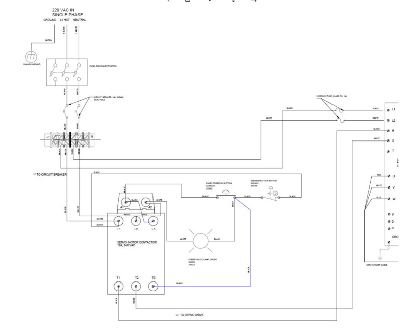
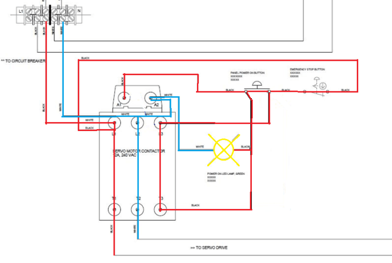
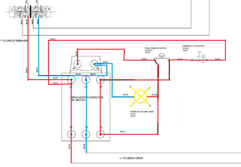
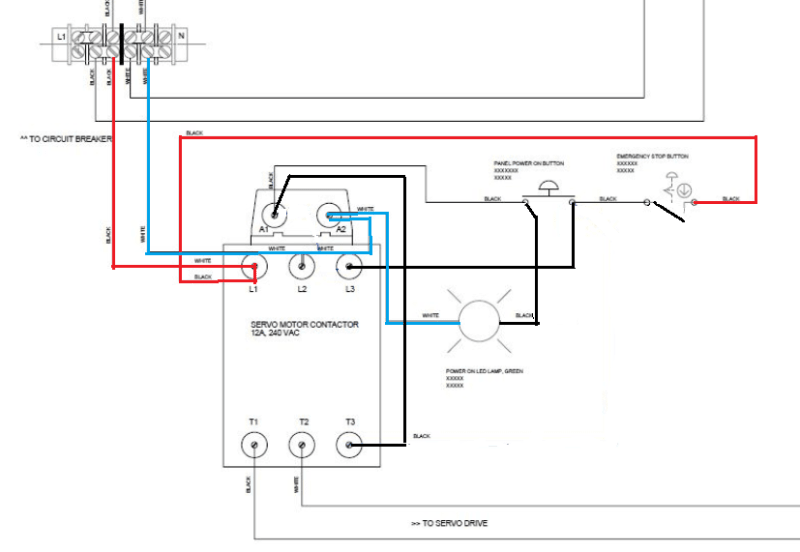
Top L is incoming supply, 220V single phase that routes through a circuit breaker.
Circuit will have a STOP, START, and an Indicator Lamp.
Bottom R is outgoing voltage to a Servo motor drive with fusing before the drive.
CB and Fuse locations are specified in the servo drive manual.
No wire numbers yet, just indicating colors; Black (L1), White (Neutral)
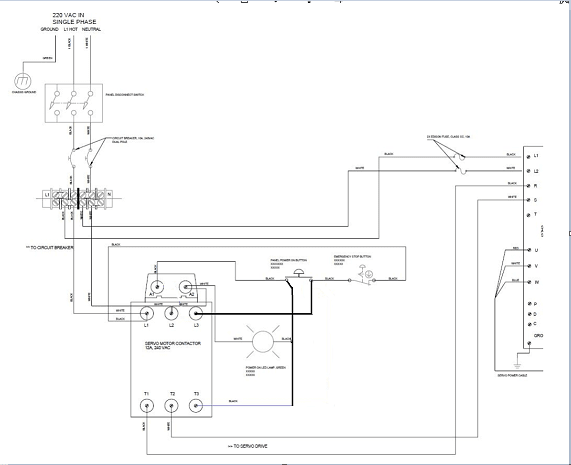
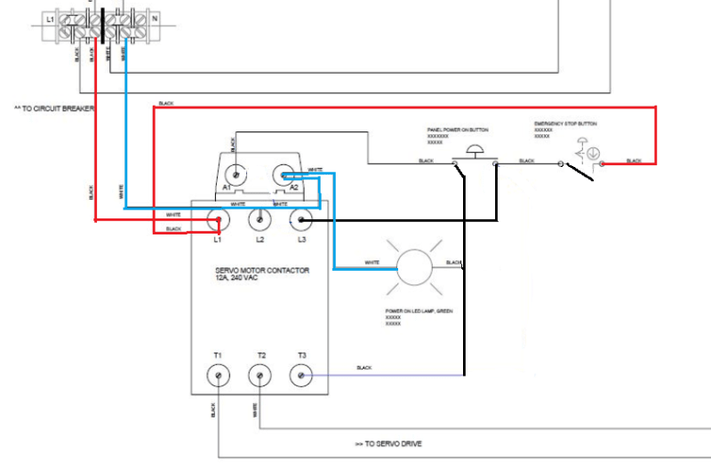
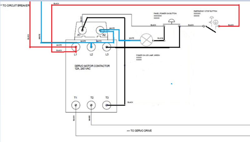
![[sleeping]](/data/assets/smilies/sleeping.gif "[sleeping] [sleeping]") so if I am wrong I am sure someone will correct me.
so if I am wrong I am sure someone will correct me.![[ponder]](/data/assets/smilies/ponder.gif "[ponder] [ponder]")
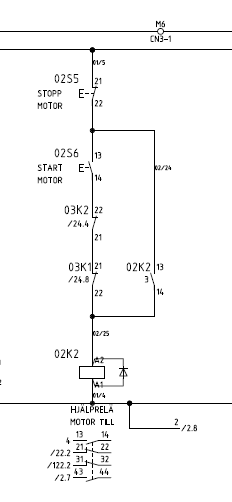
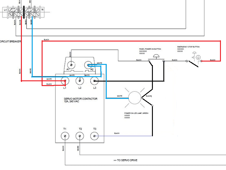
") Red Hot, Blue Neutral
Red Hot, Blue Neutral
![[lol]](/data/assets/smilies/lol.gif "[lol] [lol]")