Continue to Site

Eng-Tips is the largest engineering community on the Internet

Intelligent Work Forums for Engineering Professionals

  • Congratulations GregLocock on being selected by the Eng-Tips community for having the most helpful posts in the forums last week. Way to Go!

Motor RTD Wiring 2

Status
Not open for further replies.

Histor

Electrical
Mar 2, 2022
70
Hi,
Could you please help me on understanding the wiring of Motor winding and Bearing RTDs?
We have 250kW ID fan motor with 6 nos. of Winding PT100 RTDs. 2 Nos. of Bearing RTDs.
My MCC supplier has provided only 3 Terminals (2 + 1 shield) per RTD at at VFD. I have checked my previous projects and found that they had 4 Terminals (3 + 1 shield) for RTD wiring. Now, my Question is, is it enough to go with 3 Terminals (2+1shield) for RTD wiring at VFD? I have purchased Triad cable for this purpose. How Can I overcome this issue?
Thanks.
 
Replies continue below

Recommended for you

Usually RTDs are 3 wire, 2 for detection of wire resistance, and the 3rd for the RTD. First check the manual to see how it should be wired. The shield is usually separate and grounded at kne end only, if 3 wire, use 3 wires.

David
 
The Motor Supplier mentioned it is a 4 wire RTD.
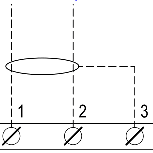
But in VFD, I Could see only 2 terminals and a shield as shown below.

RTD_terminal_f1h2h3.png


Please let me know if a 4 Wire RTD can be connected with the terminals shown above? If I can, what will be the impact? Thanks.
Please note that the motor and VFD are supplied by two different suppliers.

 
Use 2 wires into each rtd, if it's a short run it will be less than an ohm, you could measure the lead resistance and determine a fudge factor for error and adjust trips accordingly. At least it's not a 10 ohm rtd, which would add errors faster. David
 
You can connect 2 wires to one of the terminals and then the RTD module will compensate for the lead resistance except for the short piece of lead from the terminal to inside the motor.
 
The VFD has a 2-wire RTD input; the VFD has no lead wire compensation functionality for a temperature calculation.

10 feet (3m) of 20g lead wire between a 2-wire RTD and the analog input on the drive has a resistance of 0.10 Ohms. Longer or shorter lengths of copper lead wire have proportional greater or lesser resistance.

The 0.10 Ohms of lead wire resistance will be added to the RTD value and become a constant offset of 0.25°C.

If 0.25°C is worth worrying about, then there might be a temperature offset in the VFD to make a correction.
 
Dear Mr. Histor (Electrical)(OP)16 Dec 22 04:08=
"... #1.We have 250kW ID fan motor with 6 nos. of Winding PT100 RTDs. 2 Nos. of Bearing RTDs...The Motor Supplier mentioned it is a 4 wire RTD...."
1. I assumed that the motor has 2pcs RTDs per phase winding (2pcs x 3ph = 6pcs) and 1pcs on each end bearing (=2pcs). Total 8 pcs of [individual] RTD. Each RTD is a 4-wire type.

"....#2. My MCC supplier has provided only 3 Terminals (2 + 1 shield) per RTD at VFD."
I assumed that the (VFD is equipped/allowed) for [8 individual RTD inputs connection]. Attention: Check and reconfirm !? .... However, each RTD input point has only 1,2 and 3 for shield terminals.

".....#3. How Can I overcome this issue?....."
3. Based on my assumption above 1 and 2; the issue is [how to connect a 4-wire RTD to a VFD provided with terminal 1,2,3 ; suitable only for 2-wire RTD]
My suggestions are:
(a) At RTD end: (i) short both Red wires. (ii) short both White wires. This action converts the 4-wire TRD to a 2-wire.
(b) connect a separate twisted pair screened copper conductor 2.5 to 4 mm2 from the Red shorting point to VFD terminal 1. Connect White shorting point to the VFD terminal 2. The screen (shield) to terminal 3.
Che Kuan Yau (Singapore)

 
I goofed, and neglected the out-and-back lead wire resistance in back-of-the-envelope calculation above.

10 Feet (3m) of lead is 20 feet (6m) out and back so the combined lead wire resistance is 0.20 Ohms (20g conductor) with a positive error of 0.50°C.

However, if che12345's suggestion to use both lead wires on each side of the RTD is used, then the lead wire resistance is reduced by a factor 2, with a resulting lead wire resistance of 0.10 Ohms and a positive error of 0.25°C.

 
Dear Mr.Histor
1. My earlier post suggest using twisted pair copper conductor 2.5 - 4 mm2 would be fine for a distance of say < 100m. Note: Min. 2.5 mm2 is for mechanical property reasons and 4 mm2 is for long distance say >100m.
2. FYI: (a) 20 AWG = 0.5 mm2 approx. Be aware of the mechanical breakage besides the resistance.
(b) A 2.5 mm2 = 14 AWG approx.
(c) A 4 mm2 = 12 AWG approx. In general, 4 mm2 would be fine covering a long distance.
Che Kuan Yau (Singapore)
 
Status
Not open for further replies.

Part and Inventory Search

Sponsor