Here is one scenario I can think of - if you have two offset-parallel holes as "common datum features" (ASME Y14.5-2018) or as they were previously called "multiple datum features" (ASME Y14.5-2009), referenced as A-B, or more practically - A(M)-B(M) in a feature control frame, one of the planes of the datum reference frame will be established coincident with the two axes of the true geometric counterparts of these holes (and another plane will be established at the middle of the distance between them, perpendicularly to the first plane).
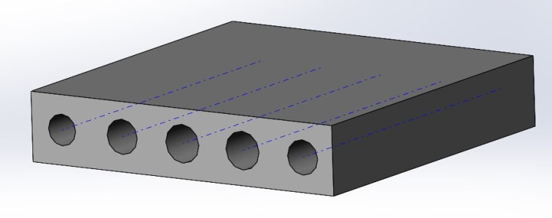
Actually yes, these are good points. The scenario I was referring to is as below. Where the axes of the 5 holes are in a plane. The top and bottom surfaces are irrelevant. The holes may or may not be of the same diameter and will contain MANY other coaxial features.
Note that all the cases where the axes are in one plane are only relevant to and useful for datums and datum reference frames, where there is a constraint that the true geometric counterparts are basically related to each other and are forced to align.
The actual axes (of the unrelated actual mating envelopes) will not be aligned on one plane.
Perhaps I am being pedantic here, but what happens if the two axes are not parallel?
To my mind, two holes define a line. If a plane is the primary datum, the line can define the location of a perpedicular datum. Two holes as a primary datum plane does not sound like a good idea to me.
drawoh,
I totally agree!!! Y14.5 doesnt't allow it! I have some mfg folks trying to tell me that this "plane" is what they need. Was wondering what the crowd thought/
Y14.5m-1994 para 4.3.2:
Datum Feature Identification. Datum features are identified on the drawing by means of a datum feature symbol. The datum feature symbol identifies the physical features and shall not be applied to center lines, center planes, or axes except as defined in paragraphs 4.6.6 and 4.6.7 (pertaining to Datum Targets).
Y14.5-2009 para 4.8.2
Datum Feature Identification
Datum features are identified on the drawing by means of a datum feature symbol. See Figs. 3-2, 3-3, and 3-4. The datum feature symbol identifies physical features and shall not be applied to center lines, center
planes, or axes.
Those prohibitions are about using the graphical depictions of axes and center lines, and center planes as terminals for the datum feature symbol. The features those depictions are related to can be terminals for the datum feature symbol.
Any group of parallel holes defines two mutually perpendicular planes that are fixed in orientation.
It is the order of the datum feature references in the feature control frames that tells which direction is the important one.
Show what that reference is intended to be in order to answer the question.
straightline101,
It is possible there is some confusion between different issues. The paragraphs you quoted are about how to place the datum feature symbol. It essentially says that you need to use the datum feature symbol to identify physical features as the part features that will be involved in simulation of datums, by placing the symbol on part feature outlines or size dimensions that define physical features of size.
On the other hand, datums (not datum features), are derived from either physical fixturing devices or a virtual simulation in the CMM software, and they are always theoretical - points, axes, planes, or combinations of such. These eventually lead to a reference system of 3 orthogonal planes, also theoretical. You didn't tell us all the details, but it's possible that the "manufacturing folks" know what they are talking about.
As for the concern raised by drawoh, about the effect of the parallelism variation, it is basically (sorry for the pun) eliminated by datum simulation rules, that require the relationship between datum simulators to be independent of variations in the actual geometries of the datum features and their mutual as produced orientation/location.
How about making your first hole as datum feature[ ]A, and your second hole as datum feature[ ]B? Datum[ ]A is your axis. Datum[ ]B is your clocking feature, and you are going to have to specify how to contact it. You need a face someone to completely constrain your part.