Continue to Site

Eng-Tips is the largest engineering community on the Internet

Intelligent Work Forums for Engineering Professionals

  • Congratulations IDS on being selected by the Eng-Tips community for having the most helpful posts in the forums last week. Way to Go!

N-Channel mosfet with TTL

Status
Not open for further replies.

jozaeta

Bioengineer
Nov 19, 2005
13
I'm trying to drive a 12V valve with a TTL signal from my motion controller. After various suggestions, I'm trying a mosfet to drive the circuit. Specifically, I am using this mosfet:
I have the TTL connected to a 10k resistor, which then connects to the gate. The source is connected to the negative end of a 12V power supply. The drain is connected to the the negative lead of the valve, with an ultra fast 100V axial diode connected in parallel with the valve. The positive lead the valve connects to the positive end of the 12V power supply.

When I power on the power supply, the mosfet appears to be already conducting, as the valve begins to dispense its fluid. Sending the 5V TTL signal appears to have no effect. What did I do wrong?
 
Replies continue below

Recommended for you

That link is useless because it is a "session" on Digikey's site. Cough up the actual part number and we can check it out.

First guess would be that you have put in the diode across the FET backwards.. The band must be towards the valve coil.

Next because FET require so little drive current just touching the board can turn them on..... So good design practice is to always include a pull down resistor between the FET's gate and ground. This assures the FET will be off unless specifically commanded on.

Also if you are running the FET from a processor ,make sure that the processor output pin is not initialized to be an output while it is also initialized to be a 1.
 
My apologies on the link. For the record, I am using the RFD16N05-ND MOSFET.

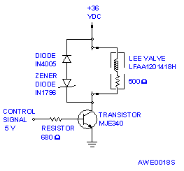
I added a connection from the gate to another 10k resistor, to ground. The FET still seems to be going. I'm unsure how to respond about the diode. In actuality, I am using two diodes, connected in series with each other, parallel to the valve, similar to this diagram (except I'm using a 100V ultra fast axial diode instead of a zener, and a MOSFET instead of a transistor; ignore the values given):

42c.gif


I am not driving the FET from a processor, just testing the circuit with a 5V source to drive the gate.
 
One: the RFD series is not TTL drive. Check the IRF series.
Two: 10k is entirely to much resistance. Usually 10-100.
Three: MOSFET's are static sensitive. They usually fail
open when overloaded, but can fail shorted if caused
by ESD. They can also be triggered on by handling,
and will stay activated until the gate charge is
drained.
Four: you show no gate return. If you do not add one, you
depend on the driver to handle the gate charge. Make
sure it is capable.
I seem to remember posting a link to driver examples once
before, but if I did not, it is:
A specific example of a low-side driver that has been
thoroughly tested and proven is:
Bear in mind that in most all the examples cited, the
implied supply voltage is 12v or more; the pages were
written toward an audience that would know the usage.
In the second drawing, you will notice an optional
"fast turn-on" modification. This is a good addition
even if you do not need the speed, since it consistantly
provides a gate return path.

MOSFET and CMOS devices are very durable and dependable,
but require different handling and drive than legacy BJT
or TTL. The learning curve is worth it. Invest the time.
<als>
 
jozaeta; I think you may have a damaged FET if it is staying on.

TTL ON voltage is pretty low like 3 volts.. So when you switch to not running this with a signal generator you need to either use a "Driver" for the FET or make sure you are using CMOS drive not TTL...
 
Status
Not open for further replies.

Part and Inventory Search

Sponsor