SteveGregory
Structural
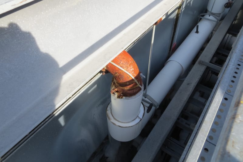
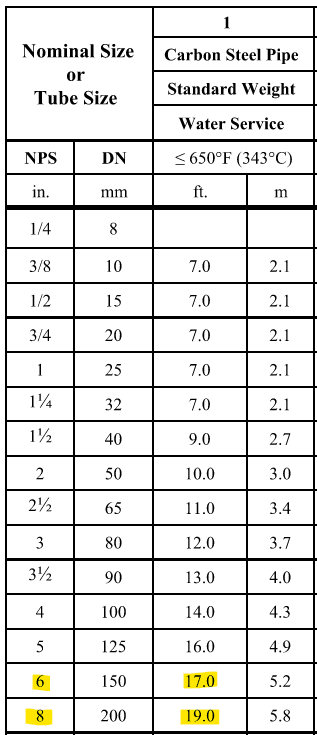
I have an unbraced W18x65 beam spanning 35'-3". It is supporting 3 pipe hangers on the bottom flange. The hangers support an insulated 6" or 8" pipe. The top of the pipe hangs down about 45" below the beam and turns up and into a cooling tower. When you push on the top flange laterally near the middle, it starts vibrating laterally.
Well, the pipe is leaking at the flange connection to the cooling tower. I can stiffen up the beam with a C12 cap channel with the flanges turned down. I am not certain this will fix the problem.
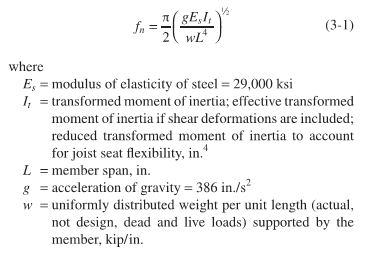
For a simply supported beam, I can calculate the natural frequency of the composite section using the equation below. To properly use the equation, I assume that I should use the beam's weak axis & channel's strong axis moment of inertia since the vibration was observed laterally. Also, the weight would only be the steel without the suspended load below since it is not vibrating vertically. Is this correct?
I am still puzzled how the vibration from the cooling tower fans could be transmitted through the pipes and up the hangers in order to excite the beam vibration.
Well, the pipe is leaking at the flange connection to the cooling tower. I can stiffen up the beam with a C12 cap channel with the flanges turned down. I am not certain this will fix the problem.
For a simply supported beam, I can calculate the natural frequency of the composite section using the equation below. To properly use the equation, I assume that I should use the beam's weak axis & channel's strong axis moment of inertia since the vibration was observed laterally. Also, the weight would only be the steel without the suspended load below since it is not vibrating vertically. Is this correct?
I am still puzzled how the vibration from the cooling tower fans could be transmitted through the pipes and up the hangers in order to excite the beam vibration.