Continue to Site

Eng-Tips is the largest engineering community on the Internet

Intelligent Work Forums for Engineering Professionals

  • Congratulations KootK on being selected by the Eng-Tips community for having the most helpful posts in the forums last week. Way to Go!

Natural Frequency Question? 1

Status
Not open for further replies.

SteveGregory

Structural
Jul 18, 2006
554
I have an unbraced W18x65 beam spanning 35'-3". It is supporting 3 pipe hangers on the bottom flange. The hangers support an insulated 6" or 8" pipe. The top of the pipe hangs down about 45" below the beam and turns up and into a cooling tower. When you push on the top flange laterally near the middle, it starts vibrating laterally.

Well, the pipe is leaking at the flange connection to the cooling tower. I can stiffen up the beam with a C12 cap channel with the flanges turned down. I am not certain this will fix the problem.

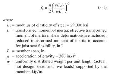
For a simply supported beam, I can calculate the natural frequency of the composite section using the equation below. To properly use the equation, I assume that I should use the beam's weak axis & channel's strong axis moment of inertia since the vibration was observed laterally. Also, the weight would only be the steel without the suspended load below since it is not vibrating vertically. Is this correct?

I am still puzzled how the vibration from the cooling tower fans could be transmitted through the pipes and up the hangers in order to excite the beam vibration.
Natural_Frequency_y4cpmd.png
 
Replies continue below

Recommended for you

271828 said:
Equation 3-1 should give a good approximation of the natural frequency for vertical motion. Include the beam, pipe, and fluid contents in plf or klf. This equation isn't sensitive to whether there are several point loads vs w. Note that this equation is used for girders with point loads. Even with two point loads, it can be used without adjustment.
,
That isn't really true - if you lump a mass at centre of the beam and neglect self weight, you get 1/(2*pi)*sqrt(48EI/m/L^3). If you plug in w*L as m you'll see the results are maybe 50%? different that equation 3-1. Here's a snippet of the equations from ROarks

Capture_cguy4c.png
 
canwesteng, wouldn't one plug in 0.5*w*L for a midspan lumped mass?

Using that, I get 1.56*sqrt[EIg / (wL^4)].

Equation 3-1 is 1.57*sqrt...

Maybe I'm totally screwing this up. Ha!
 
canwesteng, Eq 3-1 is the same as Roark's 1b in your snip for the first mode. The point was equal loads at the quarter points (3 points) is what we have with the pipe hangers. This is closer to a uniform load than concentrating all of the hanger loads into one load at the midpoint. Plus, the pipe weighs less than the bare beam and much less than a reinforced beam. So, I think a uniform load assumption is valid.

In Roark's eq. 1b above, Kn = (n x Pi)^2. If you plug this into Roark's eqn, it reduces down to Eq 3-1 above for n=1.
 
Good point - if you lump half the weight of the beam then looks like the answer is the same more or less.
 
UPDATE: I got the fan speeds today and found out that they are Variable on demand with VFD’s, 118 rpm up to 473 rpm.

Well this corresponds pretty closely to the weak axis beam frequency for Mode 1 = 2.20 Hz (132 rpm) and Mode 2 = 8.81 Hz (529 rpm). Unfortunately, the channel cap only raises Mode 1 up to 3.81 Hz (228 rpm).

I think lowering the vibration transmission through the piping might be my best solution. Next, I could weld vertical plates to the edges of the W18x65 flanges to make it a boxed beam. It will have some overhead welding on the bottom flange and everything is galvanized!

This would help the strong axis natural frequency as well. It is 9.73 Hz (584 rpm). I didn't physically observe it vibrating. But it probably does.
 
Well, it looks like I will not be able to reinforce this beam to give it a natural frequency 2X to 2.5X the natural frequency of the fans.

And there is no way to brace the beam to anything. So, the only thing left is to isolate it from the vibrations of the fan.
 
Can you use adhesives and 'glue' an elastomeric strip to the flange and glue a BAR stock to the elastomeric strip? or something of that ilk.

Rather than think climate change and the corona virus as science, think of it as the wrath of God. Feel any better?

-Dik
 
Is your pipe support structure separate from the fan structure? Have you determined if the vibration is coming thru the pipe or the pipe support? Maybe a spring support.

Screenshot_zr8h1d.png
 
GC, Yes, the pipe support beam is positioned between 2 cooling towers. The beam is fastened to the top of the screen wall framing at each end. The pipe it is supporting runs parallel to the beam and about 45" below the beam. There are 3 hangers roughly 10' apart.

Besides the isolators on the hangers and a flex connection at the cooling tower, I thought about bolting a series of heavy plates to the web if the W18 beam. These plates would function as a mass damper without changing the moment of inertia. The goal would be to reduce the frequency to about 75% of the lowest frequency of the variable speed fans in the cooling tower.

Dik, I am not sure what you had in mind. Were you thinking pipe flange or beam flange (top or bottom"? Were you thinking about adding mass similar to what I was describing above?
 
Status
Not open for further replies.

Part and Inventory Search

Sponsor