HTURKAK, thanks a lot for your response.
I've been thinking about this the last few days and have done a bit more work on this, so just wanted to share some comments:
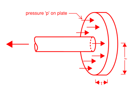
[li]I agree that 'bar diameter ~ 0' is a pretty gross simplification, but one that I expected would lead to a more conservative failure load of the anchor plate. Introducing another yield line around the base of the bar gives the following critical pressure on the plate: p_crit = [48*Mu*r]/[(2*r-db)^2*(4*r+db)], where db is the bar diameter. For db = 0, this brings us back to the original result of 3*Mu/r^2 as would be expected. For the example above, this leads to a critical pressure of 122 MPa compared to the previous estimate of 68 MPa, about 1.8x larger. This is more significant than I originally had thought and is more in line with what the FEA shows (see below).[/li]
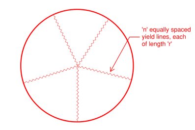
[li]As you correctly pointed out, assuming the simplest case (n = 2), i.e. the plate folding in half along a diametrical yield line, the critical load is found to be the same as if you assume an infinite number of yield lines (in the example, 68.4 MPa). However, I don't think this is a realistic failure mode. I believe the 'dishing' failure mode predicted by n = infinity is most realistic and is reflected in the FEA (below). Still, it's interesting that it predicts the same collapse load. It's also worth pointing out that the case you checked (n = 2) is not 'pyramidal' so it can't be calculated by the method I proposed (which is not to say it isn't valid). I have gone through my working again, and indeed the case for small n (i.e. = 3, 4, 5, etc.) all fairly well overestimate the collapse load. It is not until you get to about 7+ yield lines that you would get something close to the critical case. By this point, the yield lines have turned more into a yield 'cone', which is what the FEA predicts.[/li]
[li]Could you provide a reference for the suggested thickness being t ≥ 1.5 D? The anchor diameter being 3.3x the bar diameter gives a net bearing area of 10x the bar area, which I believe a lot of the codes specify to achieve the short anchorage. Looking at some of the proprietary products, e.g. Ancon bar anchors, the anchor thickness would be 20 mm for a 16 mm bar, but possibly this is to achieve enough thread length rather than being a stiffness or strength requirement? As you will see from the FEA below, for a plate thickness of just 0.6xdb, the tip displacement is in the order of 0.1mm, which I would consider a reasonable target. It is comparable to the 0.1mm slip allowed for a threaded coupler.[/li]
[li]Another thickness concern is punching shear of the plate. By my quick calculations, the plate thickness should be at least t >= 0.4*(fy_b/fy_p)*db, where fy_b and fy_p are the yield strength of the bar and plate respectively. Assuming Grade 500 bar and Grade 250 plate, this requires a plate thickness of about 0.8*db.[/li]
[li]I agree in principle with your comment about the plate stiffness being important (I would not say
more important). But I would say that for any anchor plate that has been designed to satisfy strength (i.e. satisfies the minimum punching shear and collapse load), the required proportions will basically guarantee that it will deflect a very small amount (<0.1 mm).[/li]
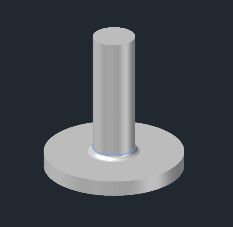
As per your suggestion, I have checked a few cases with FEA using solid elements and elastic-perfectly plastic material behaviour to best replicate the yield line analysis.
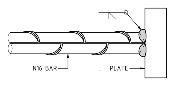
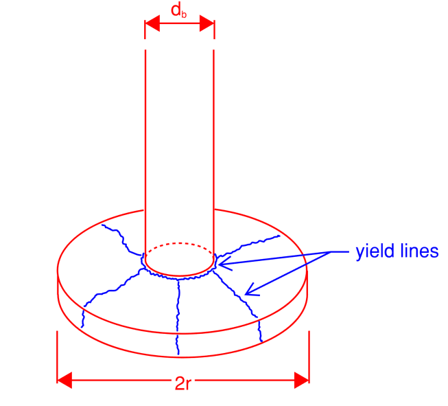
Bar is assumed to be fully butt welded to the plate (as per sketch below), with a small radius (2 mm) added to the model to give it a smooth transition.
Example: 16 mm bar, Grade 500; 53 dia x
6 thick anchor plate, Grade 250
I deliberately under-sized the plate thickness to cause the dishing-type failure, as it was proving hard to recreate this failure mode using the previous 16 mm plate example (without first yielding the rebar)
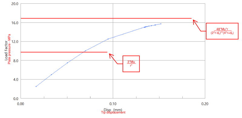
Critical pressure according to p_crit = 3Mu/r^2 is equal to 9.6 MPa.
Critical pressure according to p_crit = [48*Mu*r]/[(2*r-db)^2*(4*r+db)] is equal to 17.1 MPa.
You can see the graph of plate pressure vs tip deflection below.
The critical pressure is pretty close to the 17.1 MPa predicted by the more refined yield line model.
Tip displacement is in the order of 0.2 mm at the ultimate load, which may considered large at least compared to the 0.1 mm slip allowed for threaded couplers, for example.
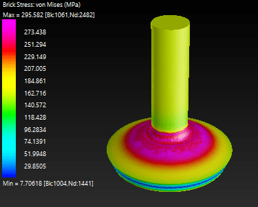
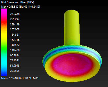
Deformed shape and von Mises stress shown below:
Based on the more refined model, a ~10 mm thick plate (~0.6*db) would be required to satisfy strength. The tip deflection for this plate is close to 0.1 mm at the ultimate state, which in my view would be reasonable. However, the punching shear requirement is actually more onerous, and would required a plate thickness of 0.8*db > 12.8 mm.
Anyway, to sum all this up - I believe that the
bare minimum plate thickness should be as follows (assuming Grade 500 bar and Grade 250 plate, and a net bearing area of 10*Ast):
[li]To avoid plastic collapse of the plate ~ t = 0.6*db[/li]
[li]To satisfy punching shear in the plate ~ t = 0.8*db[/li]
[li]To satisfy ~0.1 mm tip deflection ~ about 0.25*db^(4/3), assuming the tip deflection is inversely proportional to t^3[/li]
Of course, I don't suggest that a critical element like a reinforcement end anchor should be designed to its bare limit. I would always be more than happy to adopt similar anchor proportions to the commonly available proprietary products, but it's at least good to know what's up your sleeve.