Continue to Site

Eng-Tips is the largest engineering community on the Internet

Intelligent Work Forums for Engineering Professionals

  • Congratulations SSS148 on being selected by the Eng-Tips community for having the most helpful posts in the forums last week. Way to Go!

Need Connection Tips for Bar Joist Roof on Light Gauge Walls.

Status
Not open for further replies.

Ron247

Structural
Jan 18, 2019
1,128
I have a project with Cold-Formed Wall Studs and a bar joist roof setting on the walls. This is the first time I have used the 2 together on a project and would like any general guidance about connecting them. While I am very familiar with CFS on PEMBs, light gauge studs in general is not something I have done enough of in the past to get that gut instinct I like to have when designing. As with most designs, connecting different materials is more of a challenge. The roof live is 20 psf reducible and the roof dead load is less than 6 psf so I do not have massive loads.

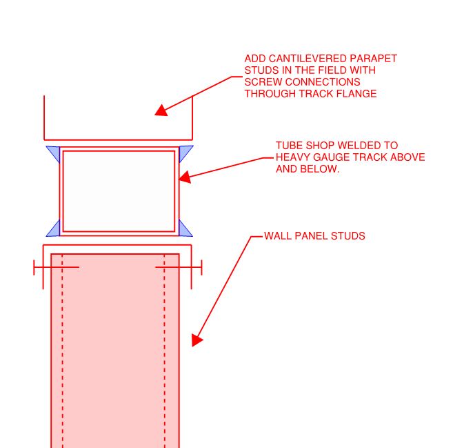
I am not sure I can have a stud under every roof bar joist so I am intending to use a HSS section on the wall as I have seen others do. The following are some issues I have already spotted in doing a preliminary review of the architectural concept they have shown. Any guidance and advice will be appreciated.
[ul]
[li]One exterior wall has a parapet made by cantilevering the wall studs. I have seen mill steel shelf angles used on the inside face for the bar joist end seats to set on. What are the preferred methods of attaching these shelf angles such as welding, PAF etc? Is there a better method where something is attached between the studs for the end seat to set on?[/li]
[li]One wall has the top sloped to match the roof pitch of 1/4:12. Is setting the bar joist end seat on that slight of a slope an issue? Is it best to let the bar joint “twist” that amount or should the joist end seat be shimmed? I have never sat a bar joist on any slope that was perpendicular to the joist.[/li]
[li]If I use the roof panel as a diaphragm, what is a good way to transfer the shear from the last bar joist to the light gauge wall that runs parallel to it? That wall is a parapet also. I feel the mill angle is a little excessive for lateral load with a light vertical load.[/li]
[li]In attaching the HSS section to the CFS track, what are the preferred methods such as welding, PAF or self-drilling screws?[/li]
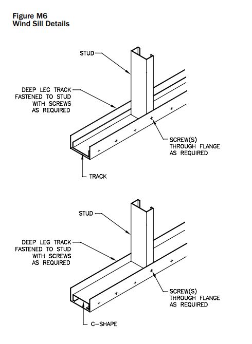
[li]What is the maximum end reaction you would allow on a heavy gauge track for 16” and 24” studs without using the HSS? I know a load can be calculated, but there are times people have maximums they use for reasons other than calcs.[/li]
[/ul]

As I stated, I am looking for some general guidance and common rules people use that deal with light gauge wall studs more than I do. Any generic details would also be appreciated especially if they show methods to connect the mill steel to light gauge steel.

Thanks in advance
 
Replies continue below

Recommended for you

I've done exactly one of these, and it was a floor, and it was flat. So not a ton of expertise here.

ron said:
One exterior wall has a parapet made by cantilevering the wall studs. I have seen mill steel shelf angles used on the inside face for the bar joist end seats to set on. What are the preferred methods of attaching these shelf angles such as welding, PAF etc? Is there a better method where something is attached between the studs for the end seat to set on?

Yuck, I don't like the sound of balloon framing the steel joists. How tall is this parapet? I might consider welding tubes onto the joist seats that cantilever up to a CFM track above to form the parapet.

ron said:
One wall has the top sloped to match the roof pitch of 1/4:12. Is setting the bar joist end seat on that slight of a slope an issue? Is it best to let the bar joint “twist” that amount or should the joist end seat be shimmed? I have never sat a bar joist on any slope that was perpendicular to the joist.

Tapered shims are an option but I'd be inclined to keep the joists perpendicular to the deck and, therefore, not plumb. You can cross bridge a couple of spots and then run regular bridging between to hold the joists out of plumb.

ron said:
If I use the roof panel as a diaphragm, what is a good way to transfer the shear from the last bar joist to the light gauge wall that runs parallel to it? That wall is a parapet also. I feel the mill angle is a little excessive for lateral load with a light vertical load.

I think I like a light, hot rolled angle for this. It is picking up a deck span after all. Maybe L2.5x2.5x3/16 welded to min 16 gauge stud flanges with 1/8" fillet welds. If you can sell it, I'd also like blocking behind the angles that completes the shear path: deck -> angle -> blocking -> exterior sheathing. That said, you would not be the first engineering to turn a blind eye to the blocking in the interest of being "practical".

ron said:
In attaching the HSS section to the CFS track, what are the preferred methods such as welding, PAF or self-drilling screws?

My one project was prefabricated walls and they preferred to shop weld the HSS to the top track rather than PAF, which I would have been fine with. The calculus may well be different if this will be field assembled.

ron said:
What is the maximum end reaction you would allow on a heavy gauge track for 16” and 24” studs without using the HSS? I know a load can be calculated, but there are times people have maximums they use for reasons other than calcs.

I haven't done enough of this to have my own "standard". That said:

1) Purchase a copy of this if you haven't already: Link

2) Unless the joists are directly over studs, supporting them on the top track gives me the heebeejeebees. I may just be a chicken on account of my limited experience with these systems.
 
KootK: The parapet is a maximum of 3' but they do not want to tie the top back to the roof, so it will have to be a cantilever design of some fashion.
 
I've done a handful - a 4 story hotel with this scheme is currently under construction. I agree with most everything KootK says. Balloon framing is a tough detail. I did it once, and my skin crawls every time I come across the detail. Fortunately the building is really small. Stopping the wall and adding a parapet above the roof feels a lot better to me. I've done it a couple of ways. You can run angles or channels up, welded to your HSS at some spacing (joist spacing is a good one to use), and then provide either a heavy enough track on top or run another piece of steel across the top and infill with studs. You're not likely to have a moment connection between the HSS and the stud below, so make sure you provide the induced moment to the joist manufacturer for consideration in top chord and seat design. The other is bracing back, which I get a lot of push back on, but is really the best way. Make sure they understand the detail. Most architects seem to think they are discreet braces that will need to be individually flashed. Once I show them that I have a brace stud for every vertical parapet stud with sheathing running up their back (essentially a GIANT cant strip), they relax and accept it.

With regard to the slope, is there no way to turn the joists so the seats are sloped rather than having the joist cocked to one side? That would be preferable if it can be managed, otherwise I agree with KootK.

At the side wall, you can either put a joist next to it with a slip connection, or a fixed connection a few feet off of the last joist (be mindful of joist camber here). If the loads are really as light as you suggest, I would try a heavy light gauge angle screwed to the studs with blocking behind it. If you can't transfer the shear, do blocking with an angle bolted to the blocking. I really don't like welding structural steel to sheet unless it's either under shop conditions or with a contractor I know and trust. Sufficiently heating the structural steel without burning up the sheet is an art it seems few can manage. Maybe the welders in your area are better?

And as for the maximum load - I won't do it. Either a stud directly underneath, or a specially designed load distribution member, as shown in the paper KootK linked to.

 
Good point, Rabbit12. TSN, Clark Dietrich, and most others have moment clips as well. We usually go with the steel as it's a bit less expensive if you already have plenty of miscellaneous steel and easier to control the load path (less torsion in the LDM), but the moment clips are a good option many cases.
 
I'd steer away from balloon framing for the parapet, the connector noted by Rabbit12 is an option SteelNetwork also makes a similar connector. However 3ft parapet will push the limits of those, may need to look into some small channels or HSS stubbed up off of the HSS distribution member.

Pitched joist with bridging is likely the way to go otherwise the sub will be fussing with the slopped deck hitting flat stepped joist top chords.

Like KootK's approach on tying the diaphragm

Seeing a lot of panelized walls lately so HSS shop welded to top track, the welds end up being a cleaner connection.

For steel joist bearing I'd always go with an HSS distribution member it will give you some field tolerance on the bearing condition that would otherwise fail a track in torsion and provide better load distribution among the studs below.

Open Source Structural Applications:
 
An idea for the parapet if the walls will be shop panelized. I tend to be pretty liberal with my short cantilevers. Granted, I'm not in a high wind zone. Sloppy, poor-man's moment connection across the tube. Not sure how well the upper track would survive shipping.

c01_ds2kak.jpg
 
Kootk, aren't you asking an awful lot of those two little #8 screws?

If the studs and joists don't align, you could align the wall studs and parapet studs and use flat strap bracing to resolve the moment.
 
phamENG said:
Kootk, aren't you asking an awful lot of those two little #8 screws?

That's the "engineering" part of the exercise. Based on some quick numbers, a thicker gauge stud and #10 screws would certainly seem feasible. Or, if one is married to a lighter gauge and #8 screws, you could got with a reinforcing block at each stud to track connection so you'd have two screws per connection.
 
I guess part of my concern comes from a consideration of the moment clips. If those clips were only there to fix the track, it would be one thing. They don't do that, though - they fix the track AND run 6-8" or more up the stud with a whole lot of fasteners. I think there may be something to be learned from their product testing.

Another way to think of it - if you put an anchor bolt with a plate washer in the track at the base of a full height wall, would you consider it a fixed end connection when analyzing the studs?
 
phamENG said:
I think there may be something to be learned from their product testing.

I don't know what to tell you other than what I've already told you phamENG:

1) I run some numbers and let them be my guide.

2) I'm pretty liberal with my short parapets.

It's not as though I'm the first person to dream up the concept. As shown below, the Steel Alliance typical details include something similar. Of course, they leave it to the designer to work out the capacity.

phamENG said:
Another way to think of it - if you put an anchor bolt with a plate washer in the track at the base of a full height wall, would you consider it a fixed end connection when analyzing the studs?

1) Would there be some degree of fixity? Of course.

2) Would I count on any fixity for practical stud design? Of course not.

3) I don't actually consider this to be an appropriately analogous condition. With a parapet, it's a strength thing and the moments are determinate, independent of relative stiffness in the system. If there's a path, there's a path. With a wall stud, you'd need the moment connection to be rigid enough, relative to the stud flexural stiffness, to justify calling the base fixed for buckling. And that's where things get considerably more questionable. Another difference, for me at least, is in the relative importance of the members. If bearing wall studs buckle, folks die. If a 3' parapet flies off in a Cat IV hurricane, you replace it.

c01_fjvteu.jpg
 

Another thing to consider with the canned moment clips is that you'd actually have to do that on the top and bottom of the HSS unless you did something funk like trying to deliver the HSS torque to the joists seats in bending. That's going to be an awful lot of clips.
 
You could install straps across the HSS member from main stud to parapet stud to take the moment couple. Shear is the only minor issue at that point which is easily handled by powder driven fasteners or TEK5's.
 
Looking at the minimum likely scenario, it appears to me that a clip would have in excess of 3X the moment capacity required for something like this. Qualitatively, that suggest to me that a lighter duty alternative might be viable.

One foot is not three foot but the second clip below shows another example where we take a few liberties with that which we consider to be non-mission critical.

c01_ydmh3j.jpg


c03_gmhm7a.jpg
 
Thanks for explaining your reasoning. For the full height stud I was thinking more of a non-bearing stud in flexure due to out of plane wind loads on the wall, but I certainly see where you're going with buckling considerations.

Around here, it's not the category IV hurricane we're concerned with - it's the several tropical or near tropical storms it'll likely see and be damaged by that will cause an owner's lawyer to come calling. Parapet damage isn't uncommon, so I guess I'm just a bit more conservative there.

I really appreciate the insight, though, and will have to consider some of those details in the future.

 
phamENG said:
I really appreciate the insight, though, and will have to consider some of those details in the future.

Don't bother considering them if you're able to sell more robust solutions in your marketplace. Where I'm at, standard practice is to provide no design at all for any parapet less than 2' tall. None. Seriously. Just whatever the installers would do left to their own devices. PAF to roof deck or whatever. The local consultants just seem to have agreed on this strategy over time.

From a Darwinian perspective, if this were causing problems and lawsuits were rampant, the design practice would not persist. That, of course, for my low wind market specifically.

phamENG said:
For the full height stud I was thinking more of a non-bearing stud in flexure due to out of plane wind loads on the wall

Even in that case, it's still a stiffness thing for me. The stud becomes a beam with a rotational spring at one end. So, again, the stiffness of the spring will significantly impact the distributions of internal actions. And I've little confidence in my ability to estimate the stiffness of the spring.

 
So far, it appears no one is comfortable with balloon framing so I am definitely going to avoid that method. The parapet height will probably accommodate building on top of the wall to form the parapet.
 
Status
Not open for further replies.

Part and Inventory Search

Sponsor