WYSIWYG67
Mechanical
- Dec 9, 2021
- 13
Hi folks,
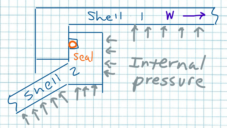
I have a problem illustrated by the attached sketch. It looks somewhat, but not exactly reminiscent of reverse flanges from Mandatory App 2 figures 2-13.1 and 2-13.2 from the ASME BPVC Section VIII-Div 1.
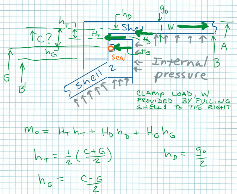
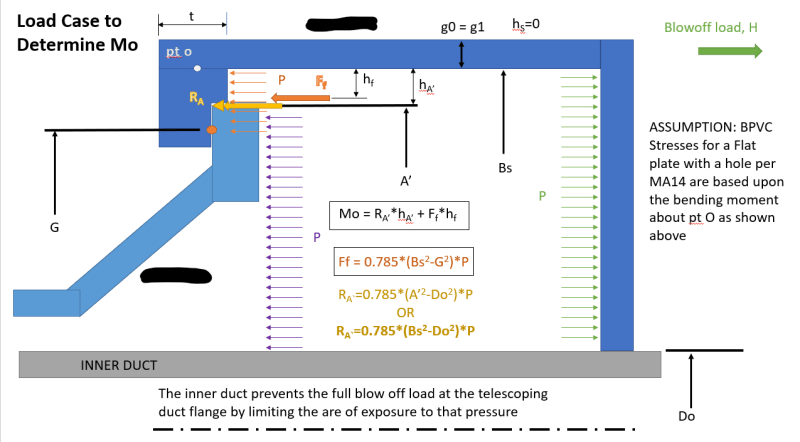
So I was trying to hammer this into a reverse flange case as described in Section 2-13 of MA2. The locking mechanism is off to the right and acts through Shell 1. So I believe the average diameter of Shell 1 would be the bolt circle (Dia C). The gasket diameter (Dia G) would be the center of the seal. I think I may be able to work out the other terms from there. I am no exactly sure how to work out where HT acts to establish hT.
I am also not too sure about the clamping load line of action for the flange of Shell 2.
Has anyone ever addressed a design like this one? Or a unique design that doesn't really match any of the figures? What is the process for this?


