Continue to Site

Eng-Tips is the largest engineering community on the Internet

Intelligent Work Forums for Engineering Professionals

  • Congratulations KootK on being selected by the Eng-Tips community for having the most helpful posts in the forums last week. Way to Go!

Need help with MA2 Reverse Flanges - Sort of....

Status
Not open for further replies.

WYSIWYG67

Mechanical
Dec 9, 2021
13
Hi folks,

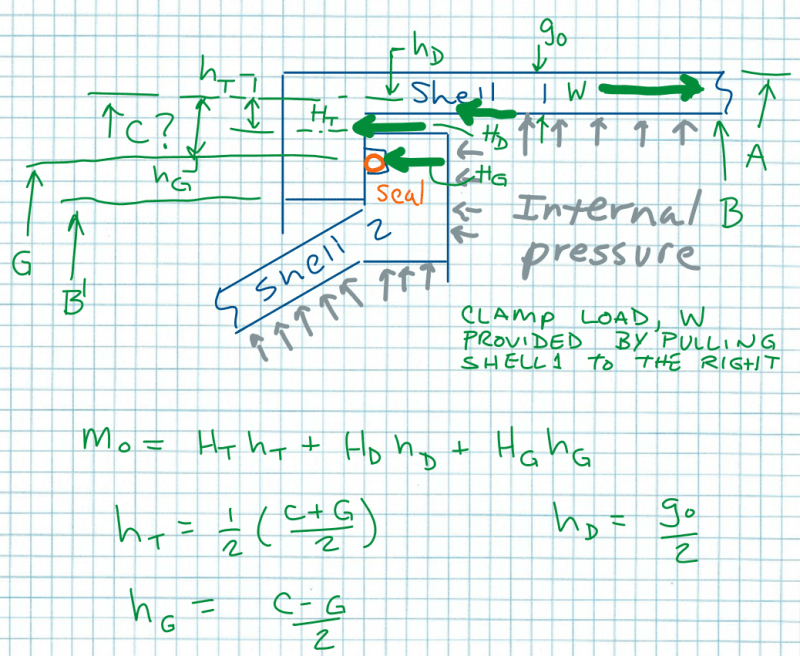
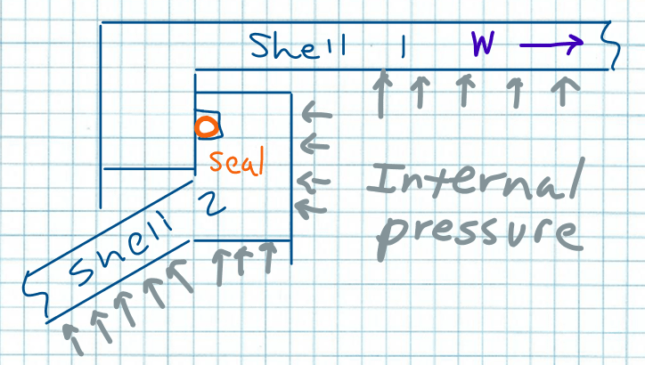
I have a problem illustrated by the attached sketch. It looks somewhat, but not exactly reminiscent of reverse flanges from Mandatory App 2 figures 2-13.1 and 2-13.2 from the ASME BPVC Section VIII-Div 1.

So I was trying to hammer this into a reverse flange case as described in Section 2-13 of MA2. The locking mechanism is off to the right and acts through Shell 1. So I believe the average diameter of Shell 1 would be the bolt circle (Dia C). The gasket diameter (Dia G) would be the center of the seal. I think I may be able to work out the other terms from there. I am no exactly sure how to work out where H[sub]T[/sub] acts to establish h[sub]T[/sub].

I am also not too sure about the clamping load line of action for the flange of Shell 2.

Has anyone ever addressed a design like this one? Or a unique design that doesn't really match any of the figures? What is the process for this?
Sealed_reverse_Flanges_qv6fe7.png
 
Replies continue below

Recommended for you

I think my free body diagram for Shell 1 looks like this. Although I have to rationalize some of the forces in my own head.

Is it true that if I am using an o-ring in a groove that it qualifies as "self energizing" and the HG load is zero?

SRF_Analysis_ngqmqq.png
 
Details are very important in this kind of applications. I assume that you are looking for quick access into the vessel. So I suggest you look for the requirements for Quick Access Closures in the code.
There are some suppliers of this kind of closures if you are interested. Search google for this.

If you are not interested in quick access, why not provide a flanged connection which is proven. If you have sufficient opening block flange face you may even use a blind flange with o-ring seal on the closing surface with a groove if the process and pressure allows.

In case you have an obliques opening you may even put an oblique blank flange inside the vessel, and lock it by two bolt on a structural member facing the flange block outside. This is commonly used for the pressurised air vessels.

As it is you only concentrated the seal option, but there are safety concerns in your application even without talking about how to fix the cover against the pressure. Code requirements for quick opening closure will give you more information.
 
It often makes more sense to design to what we have rules for, rather than try to impute rules for whatever we can design :)

Regards,

Mike

The problem with sloppy work is that the supply FAR EXCEEDS the demand
 
Thanks SnTMan. Your cautions are well taken. I usually try to live by the KISS principal. However, this is for a test facility and it is a custom closure for quick access. I would prefer to make something simpler like a bolted flange, but we are exploring several options and this is one of them. Our operations folks asked for a different solution than a bolt circle. The solution above is optimal (though risky) for many reasons in terms of our evaluation. I think we can mitigate the risk.

saplanti,

Thanks for your input. I did look at NM Appendix FF and UG-35.2. Unfortunately it doesn't really address the design calculations. Mainly redundancy and safety/locking devices of which we certainly will have. The right end of this unit providing the clamping load is planned to be a wedge and collar type of breach lock and the end I depict above will likely have some hydraulically actuated cam lock types of devices to reinforce the closure of the flange. We are planning on performing detailed FEA calculations, but I was trying to create some flange design cases that satisfy the code formulas and design methods of MA2 as a preliminary pass and to check feasibility.
 
Thanks for the links saplanti. Found some good stuff in there and some companies that we hadn't yet approached. We have fairly low temperatures, but pretty high pressures and a fairly large diameter. I can't really get into the details, unfortunately.
 
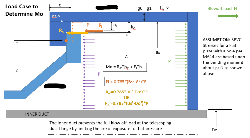
So I've been thinking about this and I think I should be able to use the MA14 rules for a flat head without a nozzle in some fashion to derive the stresses in the upper member. Does this seem unreasonable? This gets me the moment and the rest is the flange & plate constants and stress calculations per MA14 and M2 (or VIII-2 4.6/4.16). I selected A' as the diameter of the reaction because there is no fastener and as the flanges get loaded I think the flange would tend to deform and "rock" about that edge like a simple support.

Annotation_2022-02-11_165925_ehvdx3.png
 
Status
Not open for further replies.

Part and Inventory Search

Sponsor