Continue to Site

Eng-Tips is the largest engineering community on the Internet

Intelligent Work Forums for Engineering Professionals

  • Congratulations IDS on being selected by the Eng-Tips community for having the most helpful posts in the forums last week. Way to Go!

Need help with motor switch wiring, please help! 3

Status
Not open for further replies.

bradgirman

Electrical
Aug 29, 2021
12
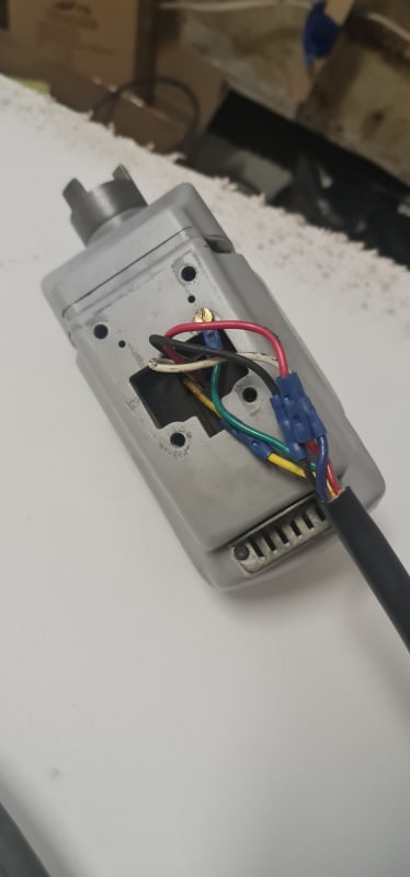
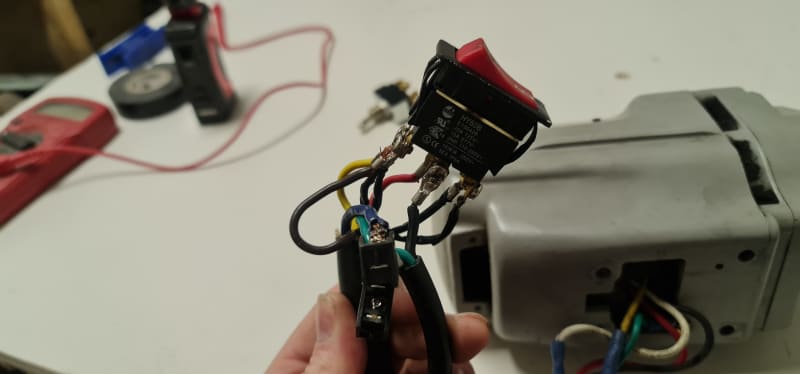
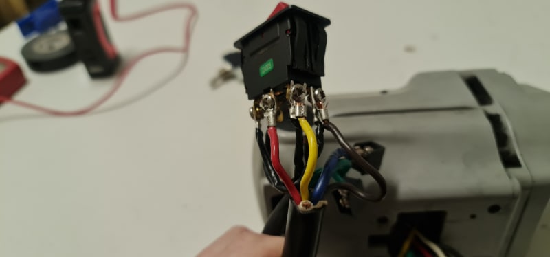
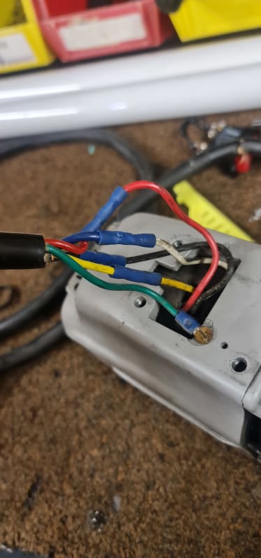
I have a motor for a stair climbing dolly I need for heavy equipment, the wiring needed to be replaced and I'm failing at wiring this properly to the rocker switch. The switch has 6 terminals, the corners are cross connected.
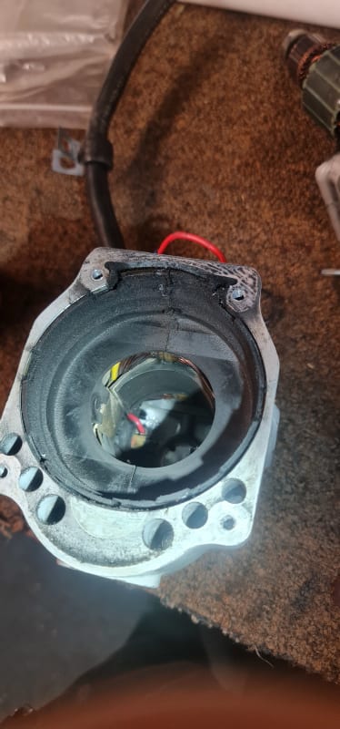
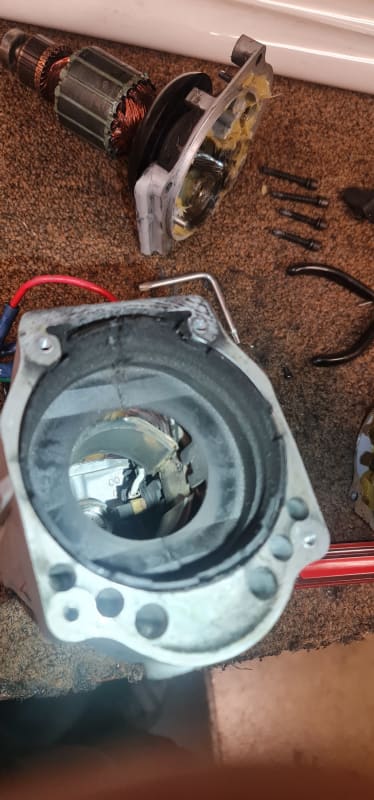
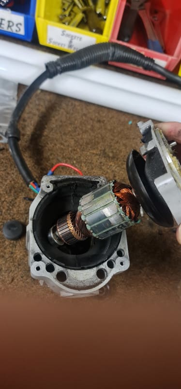
20210828_112033_cf9cqc.jpg
20210828_120439_afyudn.jpg
20210828_120434_lhkq70.jpg
20210828_120612_j0eajd.jpg
20210829_102902_joqrkp.jpg
 
Replies continue below

Recommended for you

Looks like a universal motor. The armature is connected in series with the field. So find the 2 wires that are connected to the field, say red and yellow. The other 2 wires, black and blue would be the armature. For one direction, connect the red and black leads together and apply power to the other to wires (yellow and blue). For the opposite direction, connect the red and blue leads together and apply power to the remaining wires (yellow and black). I'm guessing power is 115 Vac.
 
Arbitrary switch numbering. The numbers don't matter, the positions do.

3 4
1 2
5 6

Line one to the armature. (One of the brushes)
Armature to terminal #1. (The other brush)
Field leads to 3, and 4.
Line 2 to terminal #2.

--------------------
Ohm's law
Not just a good idea;
It's the LAW!
 
@waross
So what I have now is from the wall I have White (hot) Black (neutral) and Green (ground). I have the hot wire going straight to the right brush, it's the white motor wire that's coupled to the blue wire outside the housing. Green is grounded to the housing. The neutral wire is connected to terminal#2, field leads are connected to terminals#3 and #4, and the red (left brush) is connected to terminal#1. I'm getting no sound, vibration, or movement.
 
Do you have an ohm meter? Both the field and armature resistance should be low - probably less than 1 ohm. High resistance means bad wire or armature or field or brushes. Make sure the brushes aren't stuck in the holders.
 
@BrianE22
Unfortunately my meter is missing one of the leads :(
 
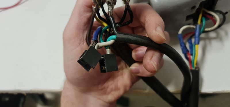
Some pics of the switch and wiring. I'm working with limited tools, supplies, and no funding😣

20210829_174951_spagwv.jpg
20210829_175018_k3qqq7.jpg
20210829_175009_kkq2qz.jpg
 
The lead for the meter is just a piece of wire. You can solder or trap one end of most any insulated wire to one switch terminal and then push the other end into the contact in the meter. Then use the other lead to check for resistance to the rest of them. It's not pretty, but it should work.
 
Used 14 gauge wire. Was able to test all connections except the field wires, everything is reading .5 or .6
 
Also, visually confirmed brushes are making contact with the armature as well as opened the brush cover and pushed on them a few times to make sure.
 
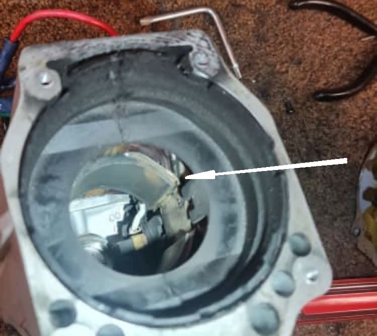
One of the blurry photos suggests a field coil is burned up... also showing what appears to be discolored laminations from the heated winding.

John

FIELD_jwyunt.jpg
 
I've been trying to get to the field writing but am unsure on this unit how to pull that out.
 
The field should be connected to 2 of the leads on your black jacketed cable. Just check at the leads. First pull them off the switch.
 
The field connection appears buried under some paper, the only black lead I have exposed is the switch end of that black jacketed cable.
 
Not black "lead", but black "jacketed" cable - the round cable that holds the black, blue, red, yellow and green wires from the motor (at the switch). Your first pictures show easy access to those wires.
 
Ahh, I see. The field is connected to the yellow and black wires and I'll test those.

Pulled everything off the switch, resistance between the two field wires (black and yellow) is 1
 
I also checked the connections on the commutator reading a fairly consistent 1.5 all the way around, no conductivity between the commutator and armature, and resistance on the wires to the brushes (red and white) is also 1.5.
 
So, the field (black and yellow) reads low ohms (still could be faulty but would at least hum or blow a fuse). Also your armature/brushes (blue and red) leads read low ohms. With that your motor should at least hum or blow a fuse. I'd apply 115 VAC direct to the motor (pull 4 leads off the switch first). Careful, the motor will produce a lot of torque when first started up - hold it tightly.

If it still doesn't hum or run or blow a fuse then there is a problem with the armature or field or brushes or leads. The meter ohms test might be getting fooled if a winding is shorted to ground.

I just saw your last post. There should be conductivity between the commutator and the armature. The armature wires are coated with an insulating varnish and individual insulation in the wires so the ohm meter might not be getting through to the wires. Measure the wires at the connection to the commutator.
 
Status
Not open for further replies.

Part and Inventory Search

Sponsor