Continue to Site

Eng-Tips is the largest engineering community on the Internet

Intelligent Work Forums for Engineering Professionals

  • Congratulations KootK on being selected by the Eng-Tips community for having the most helpful posts in the forums last week. Way to Go!

Netherlands cranes collapse 5

Status
Not open for further replies.
Replies continue below

Recommended for you

Is it just me or is the far crane's barge listing heavily in the direction the crane failed? Otherwise I couldn't see any reason for the crane to seem to uncontrollably swing to that side and ultimately fail.

Maine Professional and Structural Engineer
American Concrete Industries
 
See this which is more complete footage.

It seems they're trying to first lift then rotate the bridge section 90 degrees which is when it stats to go wrong. Not clear if the far crane failed or moved due to the lean of the barge, but as it rotates it can be seen that the bridge element is no longer level and then it all starts to go wrong.

The movement of the bridge section looks quite fast to me, especially with a 90 degree turn involved when the cranes are sitting on barges which are far from steady.

Remember - More details = better answers
Also: If you get a response it's polite to respond to it.
 
Looked like the CG shift flipped the first crane, the bridge beam hit the second crane and flipped it.
 
A little bit of barge tilt, a little bit of P-delta, repeat.
There are indeed flotation calculations available to present just this sort of thing. Insurance works also.
 
A crane is typically is lashed to a barge very securely with wire rope. The worst case should be:

The barge lists, the load swings away from the crane's cab, boom angle with the horizontal decreases. The crane's lifting capacity for this new geometry is lower than it was. The lashings keep the crane in place on the listing barge until the crane boom "folds" which causes the load to fall to earth (or the bottom of the water). Of course this removes the load allowing the barge, with the crane lashed to it, to right itself. But that is with one crane doing all the lifting - using two cranes complicates matters. In any event, the crane operator(s) need experience and "nerves of steel" to manage this fast-moving, controlled failure - it can be done.

For this accident, both of these cranes appear to be undersized truck cranes with hydraulic booms greatly extended. The outriggers on both cranes appear to have been properly extended, but there is no visible indication that either crane was secured to the barge(s). A crawler crane with a fixed-length lattice boom is a better choice for barge work - boom action is more predictable, especially under emergency conditions.

To me, it looks like each crane was on its own barge... as it should be. Also, the cranes appear to have been positioned at the "back" end of the barge... again as it should be. The barges were butted up to each other. Crane work should be performed, as much as possible, over the back of the barge not the sides - minimizes the listing problem. Ideally, the back end of the barge is blunt, not "raked". This gives maximum flotation where it is needed most. On this project, it looks like there was no choice in the narrow water way but to work over the sides.

[idea]
[r2d2]
 
Here's an aerial view from the link:

crane_collapse_aerial_seqbr2.jpg


Check out Eng-Tips Forum's Policies here:
faq731-376
 
Thank you, TME.

Here is a link to a follow up story that includes these statements:

...called the crane operators “very unprofessional and ridiculously amateurish“, adding that the operation was “doomed for failure”. “Too much risk was taken and bizarre decisions were made.”

...the crucial mistake was that the used cranes were not suitable for placement of pontoons. “These cranes are rudderless when the ground is not level. Then the operator can no longer correct the crane.”


[idea]
[r2d2]
 
You can also - in very shallow water like this, simply run pylons (outriggers essentially) down from the barge to the bottom of the canal/river/swamp.

I agree with above: Barge listed as the first and second crane rotated the load from viewer's left towards viewer's right (load passed between the two cranes); the listing (sloped deck) rotated the first crane too far, so it failed (was pulled over) AND slid off of the sloping barge deck; which dumped excess load on the second crane; which then failed.
 
As the bridge section starts to fall, part of the rigging from the second crane pulls free (top edge). As the bridge section is dropping, you can see the rigging to the second crane come taut. This is when the second crane starts sliding and tipping.

Bill
--------------------
"Why not the best?"
Jimmy Carter
 
Yeah, the second crane appears to fail mostly due to the impact and eccentric load of the falling bridge piece suddenly engaging the rigging.

Maine Professional and Structural Engineer
American Concrete Industries
 
I realize that analyzing after the fact has its drawbacks, but it seems like it would have been prudent for the contractor to install two or three properly braced outrigger pile off the side of each barge to take any overturning (keeping clear of the pick and swing area). These attachments are used on dredges all the time to keep the barge in place in wind or a current. They could have functioned as outriggers here, bearing on the bottom of the channel (hopefully).

Mike McCann, PE, SE (WA)


I've been trying to work out what they were meaning / trying to do. Looking at a number of other videos on YT, it looks like they meant to keep the bridge deck in its original orientation, then move the two barges, with those two tugs you can see, approx. 200m down the canal ( away from the video location) to where the lifting bridge is. What seems to happen is that the rear crane rotates too early and not in sync with its compatriot leading to imbalance of the load.

The actual error occurs some 10 seconds before you start to see the rear crane move but in actual fact it has been sliding sideways on the rather narrow pontoon until my suspicion is the out rigger fell off the deck causing a sudden movement , but in fact the collapse started inexorably some time before that.

It seems no one has actually died, but no mention of injuries and several buildings and businesses are affected.

The fact that the barges needed to move, with this deck held between the two gives us a bit of an idea as to why the barges weren't fixed in place, but this seems to be a poorly thought out and executed lift, with no real consequence planning

Remember - More details = better answers
Also: If you get a response it's polite to respond to it.
 
This video presumably by a drone is taken beforehand, but shows the initial position and the bridge in the back ground. It looks like they meant to lift the bridge section into the middle of the barges then move it with the cranes and lift into place.

The rear crane looks much weedier than the near one which maybe explains why it is so much closer to give it less jib angle??

Remember - More details = better answers
Also: If you get a response it's polite to respond to it.
 
LittleInch's video helps allow better speculation:

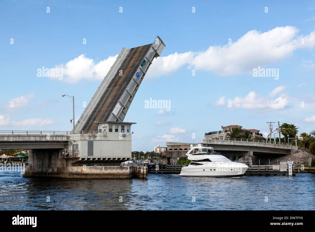
The bridge component being lifted is the movable "leaf" of a single leaf bascule bridge (drawbridge), similar to this one:

single-leaf-bascule-bridge-along-a1a-at-the-juncture-of-the-hillsboro-DW7FY0.jpg


In the videos, the barge away from the camera is narrower and more likely to list than the barge in the foreground.

The crane on the distant barge appears to be smaller (lower lifting capacity) and the outriggers are not deployed as far out as the foreground crane.

The right, back outrigger of the crane in the foreground is almost off the barge deck before the lift began. At the 20 second point in Longinthetooth's video you can see this outrigger fall off the barge deck, accelerating the collapse sequence.

In my opinion, this lift was already out of control in the first frame of the collapse video and should already have been terminated. The distant barge is listing significantly. Because of the distant crane's positioning, this puts side forces on the boom which they are not designed for.

An aside comment: On a barge of dredge the members that go straight down from the vessel to the bottom are called "spuds". They are typically used to position the vessel horizontally, but be cause of tide, current, wave action, change in vessel displacement, etc. allow the vessel to move freely vertically. For special purposes they can be used for vertical support.

[idea]
[r2d2]
 
Looking at the drone video, it gives me a "What where they thinking" impression.
On a big crane like that, you expect to have major imbalance in one direction prior to picking up the load, then in the other direction when it's lifted. And you assume that the ground is stable enough to support all that. Generally, the crane load charts don't tell you how tilted the crane can be, and still be stable and swing around and all that. So it looks like somebody maybe just assumed those barges were stable and didn't think to check for tilting there at all.
 
Slide Rule Era:

I assume the plan was to move up the canal and install the bridge section. How could this have been done differently? Such as not carrying the section vertically? Maybe laying it down on a barge from shore mounted cranes? Then lift to position again by shore mounted cranes?
 
oldestguy said:
I assume the plan was to move up the canal and install the bridge section.

Agreed, that certainly had to be the intent.

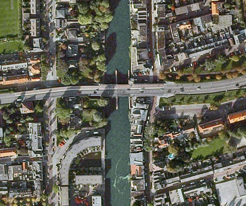
The bridge is located in an urban area. Using crane(s) from the canal bank does not look like an option. Here is a satellite photo:

Juliana_Bridge_-_Netherlands_jacysv.jpg


Other methods that could be reviewed may be:

1. Assembling the leaf in place. That was done decades ago, before very large cranes were common. Probably not cost effective now.

2. Build temporary trestle(s) adjacent to the bridge and use them to support crane(s). Again, being in an urban area limits space. Also, the waterway traffic likely has to be maintained.

3. Reinforce the adjoining bridge spans to support sizeable crane(s). Probably not cost effective.

This brings you back to barge mounted operations. I believe the Contractor was using a workable approach, he just did an unacceptable job of equipment selection and preparation. Each crane was on its own barge, the leaf was on a third barge. Failure appears to have happened when the cranes were lifting the leaf off its barge and standing it vertically on the same barge with the crane in the video background. If the leaf had been horizontal on a barge, it would be too big to maneuver into position. At some point the leaf would have to lifted to a near vertical orientation to be installed anyway.

Barge width is limited by bridge dimensions on the canal. More consideration of existing project site limitation may have allowed smaller modular leaf components to have been designed and assembled on site. Then smaller cranes could have been used - but that is hindsight.

This job, as fabricated, could have been accomplished in the way the Contractor planned. It would require much more attention to detail and careful execution.

[idea]
[r2d2]
 
Status
Not open for further replies.

Part and Inventory Search

Sponsor