Eng-Tips is the largest engineering community on the Internet

Intelligent Work Forums for Engineering Professionals

Neutral Current for CAPACITOR Unbalance Protection 1

Status
Not open for further replies.

afzumannu

Electrical
Jul 1, 2011
93
0
0
QA
Dear Engineers,

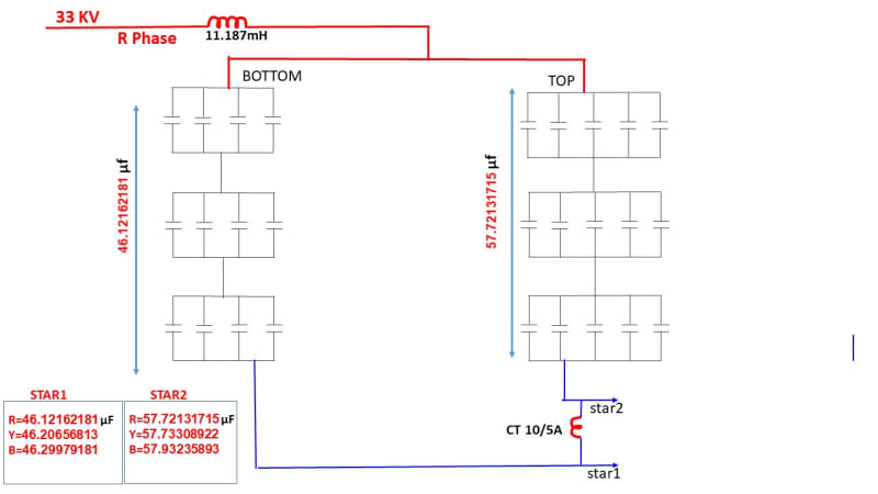
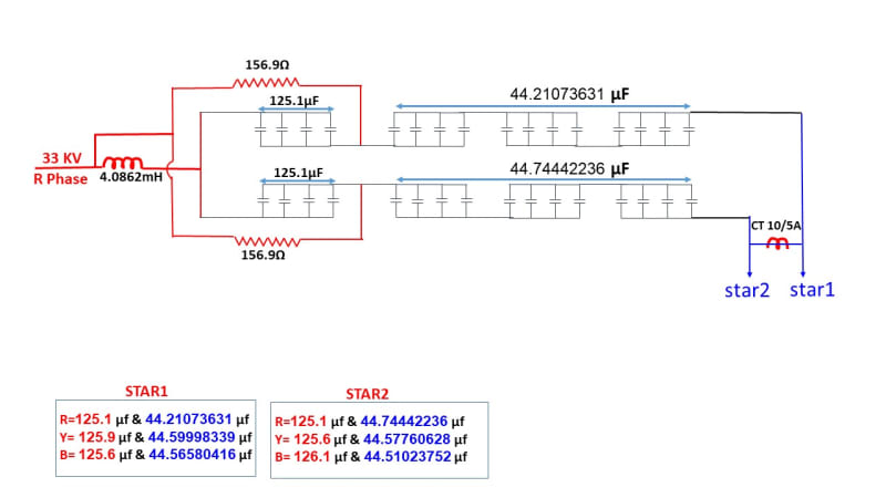
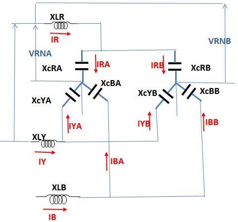
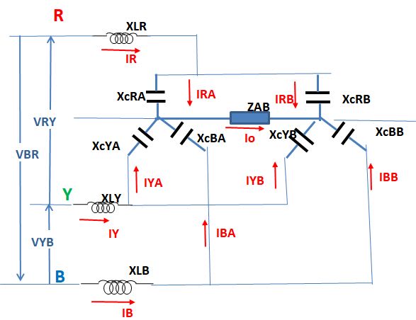
We have Filter bank line voltage is 33 KV ( 33000V), ungrounded double star connection. capacitors are connected series parallel group. each phase one row is connected to star1 and other row is connected to star2 , unbalance CT is connected in between both star point. i want to know what is the formula for neutral current flow so can understand the % of unbalance.
i know one formula that is Iunb = ( I1+I2+I3)-(I4+I5+I6), I1,I2,I3 is one star side each phase, while I4,I5,I6 is other star side. also Iunb = Un/Xc, so i will apply the values in this formula which. I have recorded the values for Xc1 = 27.2231µF, Xc2 = 27.2499, Xc3 = 26.6247 ( one group), Xc4 = 26.6499,Xc5 = 26.7749, Xc6 = 26.7747(2nd group), hence Xc=1/2πfc, here i want to know from you guys What is Un here is it 33000 V supply voltage? or individual Capacitor name plate rating, 15000V, 459 KVAR, or someone can calculate the neutral current here, any other formula let me know.
 
Replies continue below

Recommended for you

Hi,
If I am not missing something (which is very likely) I would use the following approach to calculate the neutral current.
a) Assume line infinite source (that is Zs = 0).
b) Calculate voltage at the neutral point directly using the Millman theorem.
c) Compute the neutral as the addition of currents from one star. The currents in the branch can be calculated easily knowing the line and neutral voltage.
You can do the calcs using excel (or manually).
Hope it helps

 
Filter_LC_unbalanced_hxk123.jpg

Because the general installation it is a star with non-draining neutral the sum of general currents IR,IY and IB equals zero.
Because there is a connection between the two star neutrals the capacitors A and B are parallel.
So IR*ZR-IR*ZY=VRY; IY*ZY-IB*ZB=VYB and IB*ZB-IR*ZR=VBR
ZR=XLR+XCRA*XCRB/(XCRA+XCRB) typical
By replacing IB=-IR-IY we get 2 equations with 2 unknowns: IR and IY.
The unbalance of a star current [the sum IRA,IYA,IBA] it is the neutral current and it is about
5.12 A [double than 2.53 A -approx.]
 
@7anoter4 please write the full details..I mean the Full equation because I m not perfect in complex number or attach the file..thanx
 
ZAB_included_dtell1.jpg

If ZAB≈0 then:
Define XCR=XCRA||XCRB=XCRA*XCRB/(XCRA+XCRB)
*=multiply[in Excel language]
XCY=XCYA*XCYB/(XCYA+XCYB)
XCB=XCBA*XCBB/(XCBA+XCBB)
XCRA=-j*10^6/CapRA[μF]/2/π/50 Ω [typical for XCRB,XCYA,XCYB,XCBA,XCBB]
XLR=+j*2*π*50*LR[mH]/1000 Ω
ZR=XLR+XCR [typical for ZY and ZB]
ZR*IR-ZY*IY=VRY
ZY*IY-ZB*IB=VYB
ZB*IB-ZR*IR=VBR
You need only the first and the second equation
Since IR+IY+IB=0 IB=-(IR+IY) then:
-ZB*IB=+ZB*IY+ZB*IR.
Then the equation system is:
ZR*IR-ZY*IY=VRY
ZB*IR+[ZY+ZB]*IY=VYB
VRY=33000
VYB=33000*[COS(-120)+j*SIN(-120)]
VBR=33000*[COS(-240)+j*SIN(-240)]
COS(-120)=-0.5;SIN(-120)=-0.86603
COS(-240)=-0.5;SIN(-240)=+0.86604
IR=[VRY*(ZY+ZB)+VYB*ZY)]/[ZR*(ZY+ZB)+ZY*ZB]
IY=[ZR*VYB-ZB*VRY]/[ZR*(ZY+ZB)+ZY*ZB]
IRA=IR*XCR/XCRA
IRB=IR-IRA
IYA=IY*XCY/XCYA
IYB=IY-IYA
IBA=IB*XCB/XCBA
IBB=IB-IBA
Io=-[IRA+IYA+IBA]
ZAB=CT40/1 impedance.
 
I think I well translated from Excel file[ponder].

XLR 6.80468968767549i 6.80469 0.02166 H 6.80469
XLY 6.80468968767549i 6.80469 0.02166 H 6.80469
XLB 6.80468968767549i 6.80469 0.02166 H 6.80469

XLR 6.80468968767549i 6.804689688 0.02166 H 6.804689688
XLY 6.80468968767549i 6.804689688 0.02166 H 6.804689688
XLB 6.80468968767549i 6.804689688 0.02166 H 6.804689688
XCRA -118.44353220306i -118.4435322 26.8744 μF 118.4435322
XCRB -119.441306040094i -119.441306 26.6499 μF 119.441306
XCYA -116.811396072569i -116.8113961 27.2499 μF 116.8113961
XCYB -114.603431941714i -114.6034319 27.7749 μF 114.6034319
XCBA -119.554355986655i -119.554356 26.6247 μF 119.554356
XCBB -114.60425717786i -114.6042572 27.7747 μF 114.6042572
33000 VRY 33000 33000 0 0 0
33000 VYB -16500-28578.8383248865i -16500 -28578.83832 -2.094395102 -120
33000 VBR -16500+28578.8383248865i -16500 28578.83832 -4.188790205 -240
XCR -59.4701633059733i
XCY -57.8484403730303i
XCB -58.5134920943594i
ZAB 0 0 0
IR 181.193023656591+316.561509343617i
IY 186.949749559523-319.885156593323i
IB -368.142773216114+3.32364724970603i
IRA 90.9765059039854+158.944640596964i
IYA 92.5830167582993-158.416541789382i
IBA -180.180128715521+1.62669277472267i
IRB 90.2165177526056+157.616868746653i
IYB 94.3667328012237-161.468614803941i
IBB -187.962644500593+1.69695447498336i
Io -3.37939394676368-2.15479158230468i
 
In my opinion, the actual impedance includes the reactance-as above calculated-but also a parasite resistance due to supply cables, dielectric losses [tanδ],coil winding resistance. A 2-3% unbalance of this parasite resistance may reduce the neutral current to 2.5 A .
 
Belal_zhakdf.jpg

Dear @ beyond86, please can u calculate the neutral current same as before and send me the slx file for the attached drawing and parameters, i shown only one phase with details and all the phase are same, source 33 kv, 50 Hz, Inductance- 11.187mH, Capacitance mentioned in diagram
 
Thanx @Beyond
the Values are very near,
but my question is i put the Capacitance and Inductance Values in your previous file but not coming, very wrong answer coming, i put the values for branch capacitance and Inductance.
but in this new file its coming, why? even circuit is same, this i want to know. but this time CT measure Graphic file not generated. please reply
 
belal_100_HZ_ayt9kv.jpg


Dear Beyond, the above circuit is little different as resistance also in circuit. i mentioned the Values of each phase each branch, showing only R phase the arrangement is the same for all the phase. Resistance are same in all phase 156.9Ω and inductance also same 4.0862mH. only capacitance values different which mentioned in the table, source 33 KV, 50 HZ, this is the last circuit if i will get the SLX file it will be good.. also the previous if you reply it will be good.
 
I dont know sir this is different circuit even each branch capacitance has 2 values in between resistance connected..I need exact file where I can put just the values and get the result.if I will get this circuit file, it will be very helpful for me.
 
@beyond..I have downloaded Matlab trial version it is for 30 days which is expiring this month. I want to know you sent me already sone slx file...is this will work after expiring this trial licences? Or it will not open after trial days finish, please clarify me.
 
Status
Not open for further replies.
Back
Top