afzumannu
Electrical
- Jul 1, 2011
- 93
Dear Engineers,
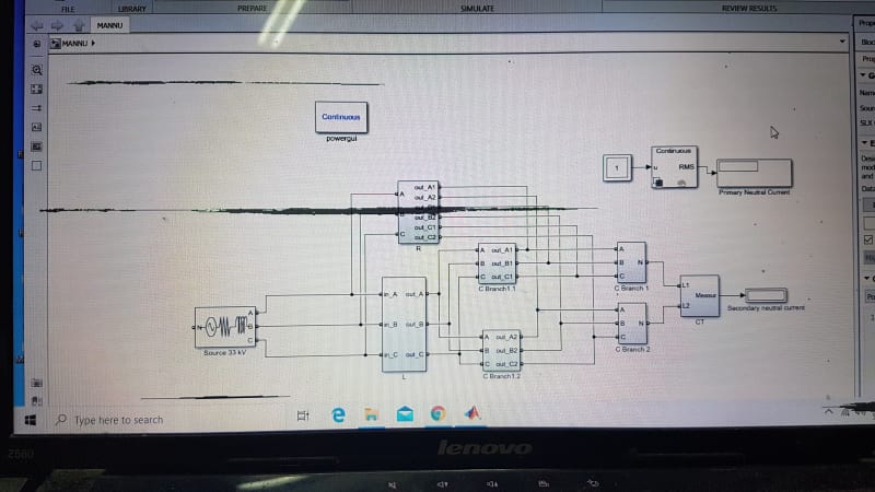
We have Filter bank line voltage is 33 KV ( 33000V), ungrounded double star connection. capacitors are connected series parallel group. each phase one row is connected to star1 and other row is connected to star2 , unbalance CT is connected in between both star point. i want to know what is the formula for neutral current flow so can understand the % of unbalance.
i know one formula that is Iunb = ( I1+I2+I3)-(I4+I5+I6), I1,I2,I3 is one star side each phase, while I4,I5,I6 is other star side. also Iunb = Un/Xc, so i will apply the values in this formula which. I have recorded the values for Xc1 = 27.2231µF, Xc2 = 27.2499, Xc3 = 26.6247 ( one group), Xc4 = 26.6499,Xc5 = 26.7749, Xc6 = 26.7747(2nd group), hence Xc=1/2πfc, here i want to know from you guys What is Un here is it 33000 V supply voltage? or individual Capacitor name plate rating, 15000V, 459 KVAR, or someone can calculate the neutral current here, any other formula let me know.

