Continue to Site

Eng-Tips is the largest engineering community on the Internet

Intelligent Work Forums for Engineering Professionals

  • Congratulations KootK on being selected by the Eng-Tips community for having the most helpful posts in the forums last week. Way to Go!

Neutral Not Included in Transformer Differential Relay 2

Status
Not open for further replies.
Replies continue below

Recommended for you

What is winding configuration (Y-Y or D-Y or D-D or Y-D) for which you are asking?
 
Most digital relays filter out 3Io via a setting. Others will wire the CT's like an EM to achieve the same.
 
Figure 2. CTs on the wye side are connected delta and CTs on the delta side connected wye. Zero sequence current doesn't leave the delta of the CT connection for primary ground faults. This also corrects for the 30 degree phase shift.
 
Delta-wye trafo, but I was talking about the X0 bushing CT. I think I answered my own questions but open to the theory.
 
Transformer differential does not include the neutral (or neutrals) and uses CT compensation to remove the zero sequence component from the phase currents. Used to be done with delta connected CTs on the wye side(s) of the transformer and wye connected CTs on the delta side(s). Today they're all connected in wye and the relay does the compensation. The big problem is that zero sequence currents can show up on one side of the transformer that aren't present on the delta side; don't want to trip for an external ground fault.

The neutral CT is very useful for REF, and that provides more sensitive protection for faults near the neutral.

I’ll see your silver lining and raise you two black clouds. - Protection Operations
 
By connecting the wye side CTs in delta, an external SLG fault on the wye side will not cause a differential trip since there will be no zero sequence current flowing outside the delta. There is no need to include the Xo CT in the differential scheme. It's been done this way for probably 70 years. With digital relays, this is not necessary - the relay can process out the zero sequence current, so CTs on both sides should be connected wye.
 
@David: How exactly does this compensation work mathematically? I've never thought about it until now.

@DPC: I can picture that, but then how does differential catch L-G faults on the secondary before the delta CT? I would think current does leave the delta connected CTs, mixes with the primary current, and it sums to zero.


The manual seems to ask for delta-delta CTs on a wye-wye unit, but I also want to understand: what happens if a wye-wye unit had wye-wye CTs. What would various faults look like to the relay? Would any of them cause an inadvertent trip?
 
Most transformer diff relays will run through the math and connections. I'd check earlier versions such as SEL 587, Basler 87T, or even HU, BDD.
 
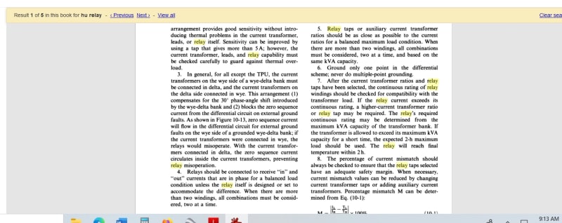
DPC, David and Thermonic1, you are correct again. Came across this:


Clipboard01_rehkmz.jpg


So how does the relay distinguish between an internal and external fault?

 
Mbrooke said:
How exactly does this compensation work mathematically? I've never thought about it until now.
Not David but..

I don’t know how to put math in here, but here goes...

Matrix 1 for example is 1/sq rt 3 times a 3x3 matrix of
1 -1 0
0 1 -1
1 0 1

I only use 1 or 11.

You choose 0-12 in the settings.
It depends on the transformer connections as to which ones to use.
 
If there is a SLG on the wye side before the CTs, only the primary CTs see the fault and the relay trips, as it should.

For a delta-delta transformer the CTs can all be connected wye. For a wye-grounded to wye-grounded transformer, in theory the CTs could be connected wye, but in a three-phase transformer there an be some "phantom tertiary" effects in the core that would cause differences in the zero sequence currents, so the CTs are generally connected delta on both sides. For a bank of three single-phase transformers, this wouldn't be a concern and probably connecting CTs wye-wye would work OK.

On the digital relays, it's nice to be able to look at the phasor diagrams of the primary and secondary to be able to confirm phasing and polarity.
 
With Regard to distinguishing between internal and external faults, the relay is still calculating a vector sum current into the zone and typically a magnitude sum (for percentage restraint type relays). Operate quantity is the vector sum and restraint is the magnitude, sometimes divided by 2 or some other factor (depending on the particular relay). It's traditional to either mathematically or through CT connections remove zero sequence currents; this is done (at a high level, without getting into the math) by performing line to line calculations. It's easier for me to visualize this with potentials which is ~equivalent - you can get 3-phase quantities from two L-L connected PTs, but if there happens to be a common offset in all three phases you won't know (draw your delta triangle, the assumption is neutral is right in the middle, but if it's shifted say 1kV in any direction you wouldn't know from the secondary quantities). this common offset is equivalent to V0, and is effectively absent in the secondary potential quantities because of the L-L connection. The same applies for currents - traditionally CTs were connected in delta on the secondary to remove the zero sequence currents and in new relays this is done through calculations like the matrix Palletjack shows.

Note this removes zero sequence currents, not positive or negative sequence, so relaying will still operate and be able to directionalize just fine for L-G faults.
 
I'm confused as to zero sequence currents being removed on the delta CTs. A single line to ground fault would produce a lot of zero sequence current (IMO). I'd think you want this current to flow over to the relay to offset the current across the two primary CTs being generated.


Can anyone draw a simple diagram with magnitude of what would be seen on the CT circuits?
 
Magnitudes are going to depend on system and transformer impedances. I attached a figure showing just zero sequence currents for a fictitious wye/wye/delta transformer, so hopefully this helps. If you had CTs on the 1.7pu side, each CT secondary would see 1.7pu @ 0 degrees. If connected in delta, the lead between the bottom and middle phase going to the relay would be +/-[(middle phase sec current) - (bottom phase sec current)] (depending on the delta orientation). So the three leads to the relays from a delta connected set of CTs effectively are providing line to line quantities to the relay. Since zero sequence by definition is the same magnitude and angle in all three phases, calculating line to line quantities will inherently remove them (1.7pu @ 0 degrees - 1.7pu @ 0 degrees = 0).

Since positive and negative sequence currents are balance three phase (with opposite rotation), they aren't cancelled by the delta connection. You're right, for a close in ground fault near a transformer with a grounded neutral you will typically see a lot of zero sequence current but if you have a lot of zero sequence, you typically will have plenty of positive and negative sequence currents too. More doesn't necessarily help. In the days of EM relays, it was prohibitively complex to include the zero sequence currents, too, in each of three operate and restraint quantities - you'd need to take the neutral current, divide by three, and sum into the operate and restraint windings; this would take an additional special transformer in the relay to separate the three portions out, and add an additional operate and restraint input to the torque calculating element. Double this for a wye/wye/delta with an X0 and H0. For a typical two-winding relay this is very nearly twice the relay parts you'd need to make it work, so twice the complexity for no clear benefit most of the time.

There are functions in modern relays that do use the neutral current, such as REF (restricted earth fault protection); I recall attending a conference where the presenter was arguing for a relay algorithm that would include the zero sequence current for higher sensitivity but I believe it needed to be slowed down a bit more than traditional differential elements; REF tends to be slower, too. If you really need the additional sensitivity, something like a sudden pressure or Buchholz relay will probably be as good or better.

 
 https://files.engineering.com/getfile.aspx?folder=d3f70def-3046-44d8-8f2f-dbe5a2ca3481&file=Capture.PNG
In a relay such as the 787 the compensation settings mimic zero sequence filter delta CTs.
The odd numbered matrices mimic delta CTs with the different angle offsets. 1 & 11 being the favorite for 30 degree leading or lagging connections.
We are changing our connections now to get all our transformers to a 0,11. (Displacement)

The even number settings mimic double delta CTs and various offsets. Never used an even number.

Going through the matrices it can be seen how the relay compensates for the phase shift.

I don’t have a clue how to post it here... may have to work it out on paper and take a pic..
 
In a delta-wye transformer, for a SLG on the wye side, the zero sequence current on the delta side is all in the delta. It is not seen by the CTs on the primary. On the wye side, there will be zero sequence current at the CTs, so the differential relay would misoperate if both sets of CTs were connected wye. When CTs on the delta side are connected wye, there is still no zero sequence current seen at the primary CT, since the Io is confined to the delta of the main winding. By connecting the wye-side CTs in delta, the Io will be confined to the delta and no zero sequence current will flow in the relay.
 
I am guessing you are talking about a classical differential, and not a sensitive earth differential, which would require a ground CT.

I don't open links, so I did not see the link.
 
Mbrooke said:
Can anyone draw a simple diagram with magnitude of what would be seen on the CT circuits?

Perhaps you could post your own diagram. Have you tried sketching this out? It should become obvious once you do so.
 
Ok, this is what I'm imagining for a delta wye trafo 0.58 pu unit come from two primary CT circuits while 1.0 pu current comes from one secondary CT across two phases. Both these currents cancel to zero in the relay?
 
Status
Not open for further replies.

Part and Inventory Search

Sponsor