Eng-Tips is the largest engineering community on the Internet

Intelligent Work Forums for Engineering Professionals

  • Congratulations waross on being selected by the Tek-Tips community for having the most helpful posts in the forums last week. Way to Go!

Nixie Tube Grid?? 4

Status
Not open for further replies.

itsmoked

Electrical
Feb 18, 2005
19,114
0
0
US
I'm tasked with designing a wacko Nixie Tube clock. I have to use the IN-28 which is a Soviet era tube that is just a single bright dot about an inch in diameter.

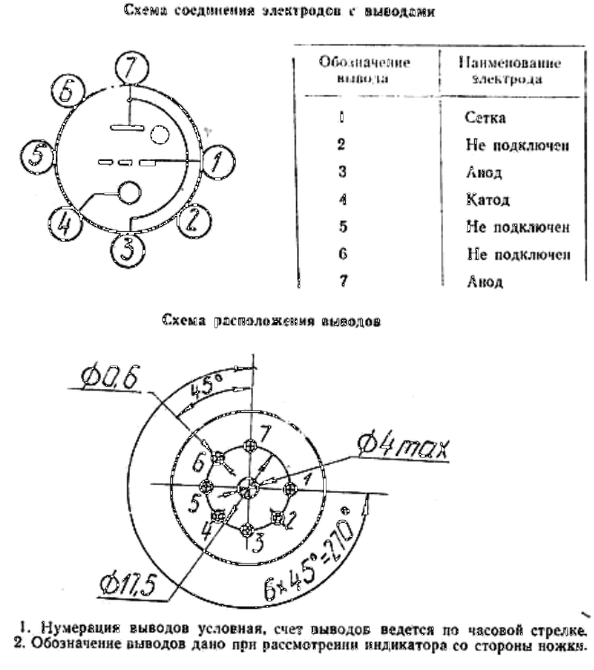
Here's the pertinent data sheet page:
IN-28_Nixie_Tube_leyy8z.png


Normally one hooks the B+ voltage to a Nixie's Anode (a metal screen) and each of the digits is a cathode that gets grounded to light it.

Well-and-fine, but this particular tube sports a Grid pin too. See pin 1 - Cetka. Cetka means 'Grid'.

Any of you tube-heads know what I should do with it? Do I ignore it?

Pins 2, 5, and 6 are NO-CONNECTION.
3 and 7 are ANODES
4 is the CATHODE

I'd be nice if anyone also knew if the diagram was viewed from below or above too. The tube is hard to see into since the sides are pretty obscured.


Keith Cress
kcress -
 
Replies continue below

Recommended for you

I wouldn't worry about an RTC, I'd just go straight crystal timekeeper. With proper tuning caps on the crystal and at indoor temps, I can easily see less than several seconds/month accuracy. Since that would only be used as a backup during the short time periods you can't get the GPS signal (a day, maybe two at the most?), most users would never notice a difference.

To me, RTCs mean loss of power protection and coin cell batteries for the backup... do you really need to go down that road?

Dan - Owner
URL]
 
Good eye IR!

RTC_gvelwc.png


I've used this RTC for years and years. It's cheap, has a bunch of static ram to keep settings in, that won't burnout like EEPROM and runs for yeeeeears on that particular battery, and won't run on the battery unless power has failed.

(I do find I have to lacquer that bit of circuit to prevent 'funny business' from bothering it.)

Keith Cress
kcress -
 
I would scrap the entire thing. And make little pizza slices. Six or twelve of them. Even two halves may work.
Make a heavy center board with all the common stuff on it. Bolt (or wide-solder) the slices ground-planes to the center and use little ribbon cables to connect to the slices.
Then, you can fit it into your process and avoid hand-soldering.
Less work. Better reliability. Better economy.

I know that you will hate this - at first - but give it a thought.

Gunnar Englund
--------------------------------------
Half full - Half empty? I don't mind. It's what in it that counts.
 
For making more than, say 10 of these clocks, the extra work in soldering jumpers between boards would be a poor ROI, in my opinion. In many cases, the extra expense in just making bigger boards is worth it. But I suppose only Keith can be the true judge of that.

Dan - Owner
URL]
 
IDC and ribbon is an alternative that I had in mind. Or board2board connectors.

The smaller size of the boards may be an important factor. That is what Keith said somewhere higher up. The board, as is, seems to be oversized for his soldering machine. But the customer may think that a "monoboard" solution is more reliable.

Gunnar Englund
--------------------------------------
Half full - Half empty? I don't mind. It's what in it that counts.
 
Well.. The boards are fabbed already. I've hand soldered dozens of SMD boards and don't actually have much problem with it other than it takes time. In this case there are actually only about 100 SMD parts and most are two pin and go really fast. I got those mondo boards for a mere $22 apiece delivered. Breaking the boards into oven - fitting pie slices would incur:

1) ~ six times the number of boards. The boards would be cheaper per but the shear quantity would likely treble the board costs if not more. Shipping one board order is ~$40. I'd be hit with $240 in shipping alone.. More than these cost in total.

2) These boards in pie shapes would likely still fill my small reflow oven with just one or maybe two boards. ~25 minutes per reflow cycle. 8 complete clocks, six slices; 48 boards. Say two fit the oven, 24 oven cycles. 24 x 25 minutes = 10 hours babysitting reflow. (Just shoot me!)

3) Would need some harnessing to convey signals to the various slices. We're talking 350 volts here which exceeds most ribbon cable systems.

4) These clocks have 204 thru-hole leads that need to be hand soldered anyway just due to the tubes. SMD solders ~3x faster than thru-hole.

I'm good. Really!

Fun discussion, thanks!


Keith Cress
kcress -
 
"$22"

It's mind-boggling how cheap, easy and fast custom PCBs have become. That industry segment deserves a medal, or a cake, or something.
 
I just realized that there's more to it than I could imagine. I fear hand-soldering small SMD like the washing machine. Could be the combination of reduced hand stability, weak sight and laziness. In other words - aging sets in.
This is another of those threads that turn every stone to come up with the optimum solution.

Gunnar Englund
--------------------------------------
Half full - Half empty? I don't mind. It's what in it that counts.
 
VE1BLL; I could not agree more!

Hi Gunnar. Indeed! Love the intelligence and broad experience the fine people here have and share.

To your list I have to include getting old adds the horror of sitting in one place for a long time which causes me butt and leg aches and pretty much is what controls the production process.

Keith Cress
kcress -
 
Status
Not open for further replies.
Back
Top