Continue to Site

Eng-Tips is the largest engineering community on the Internet

Intelligent Work Forums for Engineering Professionals

  • Congratulations KootK on being selected by the Eng-Tips community for having the most helpful posts in the forums last week. Way to Go!

No lateral load path - blocking missing above top plate 1

Status
Not open for further replies.

BubbaJ

Structural
Mar 18, 2005
163
Before I deliver some bad news to the contractor, I wanted to reach out to the group to see if there were any other options to explore.

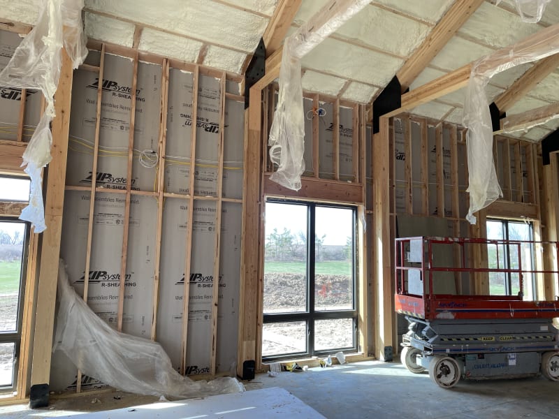
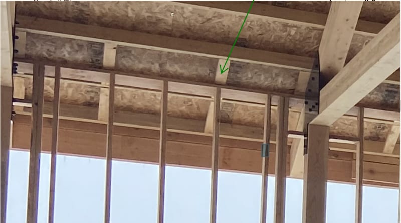
The framer took it upon themselves to ignore the drawings and the inspector noticed. Which is good, because there is no longer a continuous load path from the roof diaphragm to the shear wall. As you can see from the photos, they left out the blocking above the top plate. There are LVL trusses and columns, but they only carry gravity loads. By the time I was alerted to the problem, the roof was on and the spray foam insulation was completed.

I do not see any other solution than having them add the blocking, which will mean removing insulation and possibly roofing. Does anyone else see a different solution?
IMG_5983_whed4u.jpg


South_wall_ut6ury.jpg
 
Replies continue below

Recommended for you

KootK said:
1) Using the top plate if strapping can straddle the trusses.
What does this mean? You can't just wrap a tension strap from the top plate over the top of the truss. Even if you did, what you get 5 nails into the truss. Not adequate for the load.

KootK said:
2) Using the top plate without strapping if every wall is a shear resisting panel and would suffice in its own right.
If the top chord of the truss is functioning as a diaphragm chord, where is your drag? What is your shear transfer from the diaphragm into the top plate?

KootK said:
3) Using the facia structurally, likely by adding some tension strapping at the butt joints.
Only option I view as reasonable (excluding removing some insulation and actually giving the owner what he/she paid for).

Cutting out some foam is not a big deal.
 
XR250 said:
If each wall segment is effectively a shearwall, the load should be able to be funneled into the truss top chord by the last purlin (with appropriate clips). The truss appears to be tight against the wall top plate so it should be able to transfer through direct bearing.

For the purlin to truss connection a Simpson A35 is good for 650lb. The poster said the load at the truss is 1680lbs. No good
Not to mention the purlin likely has field nailing @ 12"oc so only 8 nails...

For the truss to top plate I'm going to assume you mean shear transfer when you said direct bearing. I think your choices are limited and the contractor will have to drill through the steel truss connector to use a tension tie or holdown like a DTT2Z (Tallow = 1825lb not my first choice but it works with a single 2x top plate).
 
Harbringer said:
What does this mean? You can't just wrap a tension strap from the top plate over the top of the truss. Even if you did, what you get 5 nails into the truss. Not adequate for the load.

What I was driving at is that one might attempt to use the top plates of the walls as diaphragm boundary elements as is ubiquitous in light frame wood buildings. As I see it, the only thing preventing the use of that strategy here is that the top plates are not continuous across the trusses as far as I can tell. That can be remedied by:

1) Verifying that the top plates are snug up to the trusses such that compression can be transferred between the top plates of adjacent walls.

2) Adding strapping such that tension can be transferred between the top plates of adjacent walls.

Used in this way, no force is transferred into or out of the truss top chord by the straps and, as such, the capacity of any fasteners into the top chords is irrelevant except, perhaps for incidental strap buckling prevention.

Harbringer said:
If the top chord of the truss is functioning as a diaphragm chord, where is your drag? What is your shear transfer from the diaphragm into the top plate?

As I described above, the top chord of the truss would not be functioning as a diaphragm chord. Let me know if that's still unclear.

In this setup, there would be no need for a drag. If every wall is a shear panel as described, you're not moving the diaphragm forces around in plan any great distance. This is a pretty common method for diaphragm design in precast/tilt-up wall systems if you're familiar with those.

Shear transfer from the diaphragm into the wall top plates would be whichever of the various options were proposed in the comments above. I believe that your point was that the shear transfer mechanisms proposed above lacked consideration of the associated boundary elements. I've just been trying to address those boundary elements, not revisit the original shear transfer mechanisms.

 
KootK said:
As I see it, the only thing preventing the use of that strategy here is that the top plates are not continuous across the trusses as far as I can tell.

The posts for the truss are not inside the wall (zoom in on the photo). I'm assuming that the designer had a top plate splice detail w/ straps as the original design included blocking above the single top plate.

KootK said:
In this setup, there would be no need for a drag. If every wall is a shear panel as described, you're not moving the diaphragm forces around in plan any great distance.

How is the wall pier with a 6' door in the middle a shear panel? Unlikely that the designer used force transfer around openings at the windows but you can't do that at doors. Without a continuous drag element the assumption of uniform distribution of shear to each wall segment is no longer valid and the relatively rigidity of each wall segment would need to be analyzed.

KootK said:
This is a pretty common method for diaphragm design in precast/tilt-up wall systems if you're familiar with those.
Not familiar with those but my position is that for wood frame construction the unsupported diaphragm unit shear over an opening in a wall has to be transmitted through a collector into a shearwall. Using a fascia as a chord and hand waving away the need for a drag is not common for wood framing construction at least in the western US.

This is a whole lot of effort just to avoid providing cutting out some foam and providing a real load path.
 
Harbringer said:
The posts for the truss are not inside the wall (zoom in on the photo).

Great, stuff some blocking in the gap if there is one and proceed with the strap in the same vein.

Harbringer said:
How is the wall pier with a 6' door in the middle a shear panel?

Who knows? Only OP. Could be segmented, FTAO, Simpson strong wall... any number of things. We're throwing out ideas here, not designing OP's building for him. If we had to limit our suggestions to only those that we were certain would work top to bottom, we'd have no suggestions.

Harbringer said:
Not familiar with those but my position is that for wood frame construction the unsupported diaphragm unit shear over an opening in a wall has to be transmitted through a collector into a shearwall.

Why can't the top plates that exist in this set up be the collectors over the openings if they're strapped together etc as proposed?

Harbringer said:
Using a fascia as a chord and hand waving away the need for a drag is not common for wood framing construction at least in the western US.

I take exception to the "hand waving" characterization. In my opinion, what we're doing here is creatively, and rigorously helping OP come up with some alternate solutions.

Believe me, I'd be all for the next edition of IBC coming out with a clause to the tune of: all diaphragms shall be detailed Terry Malone's way, otherwise we'll set fire to your building and have you start over. Sign me up. I could jack up my fees and hire an EIT to sit around and detail transfer diaphragms all week long. Until then, those of us where are not in a highly regulated, high wind/seismic area (most of us) are kind of stuck making the best of:

1) What our mean competitor deems acceptable and;

2) What, unfortunately for us, has a demonstrated history of successful performance in our markets.

Having the regulatory juggernaut of the state of California in your corner when designing diaphragms is a luxury. We don't all have that. Heck, in my home jurisdiction, we don't even have to submit calcs.


KootK said:
In this setup, there would be no need for a drag.

KootK said:
Why can't the top plates that exist in this set up be the collectors over the openings if they're strapped together etc as proposed?

Hard to debate when you take both sides of the argument.

KootK said:
Having the regulatory juggernaut of the state of California in your corner when designing diaphragms is a luxury.

You must not have done much work in California if you view it as luxurious.

KootK said:
In my opinion, what we're doing here is creatively, and rigorously helping OP come up with some alternate solutions.

I'm seeing the creativity but not the rigor.

This will be my last reply to this thread as I don't see this as being a productive discussion.
 
Harbringer said:
Hard to debate when you take both sides of the argument.

I didn't take both sides of the argument. I proposed those as two different solutions.

Harbringer said:
You must not have done much work in California if you view it as luxurious.

I do 4-6 projects in California per year. I love the regulatory attention paid to doing clean engineering. It's that aspect that I deem a luxury.

Harbringer said:
I'm seeing the creativity but not the rigor.

1) If you want to tell me what you think is missing, I'm happy to tell you how I think that it's not.

2) To a large extent, the rigor is OP's business. Out of necessity, and respect, we have to assume some level of competence on the part of our colleagues.
 
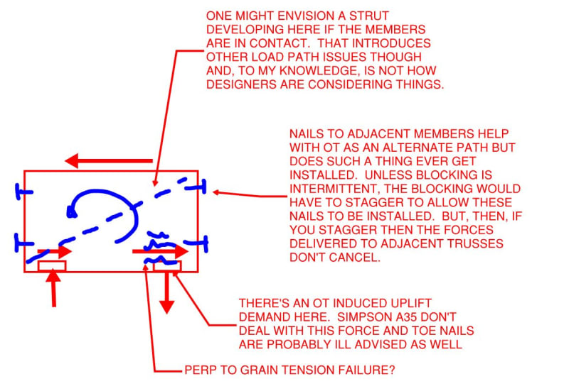
Sometimes, when I attempt to think deeply about blocking, I don't actually love what I find there. At least, that's the case for low aspect, high demand blocking. My sense is that blocking is pretty much the best of the available, practical options rather than a perfect load path. Anybody know of any testing done to specifically target the effectiveness of blocked connections?

C01_vksym9.jpg
 
@KootK,

They typically toenail the blocking instead of end nail it for the uplift.
When you say "stagger" do you mean offset by 1 1/2"? If so, why would that prevent the forces from cancelling?
 
Do they actually toe nail the blocking ends by default? If so, I like that. I'll have to start showing that in my details explicitly I guess. Would that require web blocking on a TJI or just nails into the flanges? I know you don't favor TJI's...

Replace "stagger" with "alternate spaces" for the bit on force cancelling.
 
I suppose web blocking. Yea, I despise TJI's
I typically do show the blocks staggered 1 1/2" if possible so they can be end-nailed. Otherwise they are typically toenailed.
 
Status
Not open for further replies.

Part and Inventory Search

Sponsor