Navigation
Install the app
How to install the app on iOS
Follow along with the video below to see how to install our site as a web app on your home screen.
Note: This feature may not be available in some browsers.
More options
Style variation
-
Congratulations cowski on being selected by the Eng-Tips community for having the most helpful posts in the forums last week. Way to Go!
You are using an out of date browser. It may not display this or other websites correctly.
You should upgrade or use an alternative browser.
You should upgrade or use an alternative browser.
Non-linear loads and neutral current 4
- Thread starter Mbrooke
- Start date
- Status
- Not open for further replies.
protoslash
Electrical
Cuky, your last diagram contradicts with your first post in this thread.
OP, I think it is settled that no neutral current to your original question.
OP, I think it is settled that no neutral current to your original question.
- Thread starter
- #42
I'm also leaning toward that, but part of me says there is as I can't see the harmonics circulating within the load due to the impedance of the load.
I ask because in Line-Line connected systems (like those used in the Philippines and South America) Y grounded primary transformers would be a welcome thing as ferroresonance (or lack there of) would no longer limit distribution voltages to 15kv and under.
I ask because in Line-Line connected systems (like those used in the Philippines and South America) Y grounded primary transformers would be a welcome thing as ferroresonance (or lack there of) would no longer limit distribution voltages to 15kv and under.
protoslash,
Perhaps we can call it a correction instead of a contradiction. We're all allowed to learn here.
Mbrooke,
Basic transformer theory. Take your secondary winding triplen current (zero), multiply by LV/HV to find the primary winding current (zero), multiply by 3 to find the primary neutral current. Zero is the answer.
- Thread starter
- #44
- Moderator
- #45
That's great.
A solution to many harmonics issues.
We will design our non linear circuits to be connected phase to phase and forget about triplen currents reflected to the grid.
I guess we should have been connecting ballasted lighting phase to phase instead of phase to neutral.
Bill
--------------------
"Why not the best?"
Jimmy Carter
- Thread starter
- #46
I'd be careful applying non-linear loads phase-to-phase to avoid 3rd harmonic currents in the line. The equipment manufacturer may require that single phase equipment be supplied by a grounded source. Non-linear three-phase loads like VFDs normally employ 6 pulse rectifiers that do not create 3rd harmonics anyway.
Certainly be careful applying single phase loads in an ungrounded wye configuration. This has been mentioned, and included as Case 2 in cuky's diagram. Cuky's Case 2 does not mention triplen harmonics in the load, but if there aren't any in the line and transformer windings, then there aren't any in the load either. What happens if you connect loads that normally produce 3rd harmonics in an isolated neutral configuration? Like lighting ballasts and computers. I think that the floating neutral will shift erratically within each cycle. The resultant voltage distortions will have the effect of suppressing triplen currents but also would probably really screw up operation of the equipment.
Keep in mind that we aren't talking about loads that produce nice sinusoidal currents of different harmonic frequencies. We are talking about loads that distort the current within each cycle. The loads can be analyzed mathematically by considering them to be sinusoidal current sources at different harmonic frequencies.
- Moderator
- #49
-
1
- #50
Good luck,always.
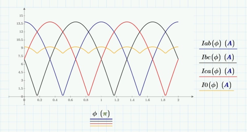
Per Jghrist's Oct 2 statement, I decided to look at a more realistic load using Mathcad. Connecting full wave bridge rectifiers in series to resistive loads, all connected line to line, I get:
and:
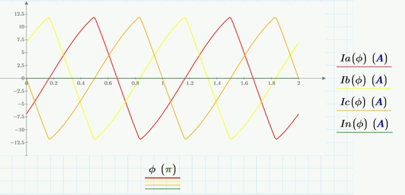
Triplens are gone from the lines, but it's still distorted. Not sure how much we've gained with this connection.
Per Jghrist's Oct 2 statement, I decided to look at a more realistic load using Mathcad. Connecting full wave bridge rectifiers in series to resistive loads, all connected line to line, I get:

and:

Triplens are gone from the lines, but it's still distorted. Not sure how much we've gained with this connection.
- Thread starter
- #51
Thats my thinking, its still distorted.
I hate to question most of whom are WAAAY smarter then I am... but I feel as though this distortion may cause some current to flow. Thats what my gut tells me, but again my understanding is thin.
In my eyes, the primary wingdings are simply none linear.
I hate to question most of whom are WAAAY smarter then I am... but I feel as though this distortion may cause some current to flow. Thats what my gut tells me, but again my understanding is thin.
In my eyes, the primary wingdings are simply none linear.
Stevenal,
I'm not clear about what the currents represent. Is Iab(Ø) the current through the rectifier or the rectified current through the resistance load? It is all positive, so it must be the rectified current. I would think that the current through the rectifier would be an undistorted sine wave. I don't know what I0(Ø) is.
Ia(Ø) would be the difference between Iab(Ø) and Ica(Ø) as they go into the rectifier.
I'm thinking of doing a similar calculation, but with the distorted input to a switch mode power supply. There is an example waveform in IEEE-519.
The following should be expected for 3-phase balance non-linear load:
1) Neutral Current (Load & Transformer):
1.1 The load and transformer neutral current to ground is zero since there is no neutral connection between the transformer and the load. Therefore, there is no path for the triplen harmonic current generated at the balance non-linear load to flow into the ground [highlight #FCE94F] (IG = Ig = 0)[/highlight]
2) Line Currents (Load & Transformer):
2.1 There is a phase current flowing in the line from the transformer to the load. [highlight #FCE94F] (IΦ ≠ 0)[/highlight]
2.2 The ac line currents do not contain dc or triplen harmonics. [highlight #FCE94F] (Itriplen+ Idc = 0)[/highlight]
3) Neutral Voltage:
3.1) There is induced voltage between the neutral load to ground [highlight #FCE94F](Vn ≠ 0)[/highlight]
3.2) The voltage from the transformer neutral to ground is nule since is solidly grounded [highlight #FCE94F] VN = 0)[/highlight]
-
1
- #54
Three separate rectifiers connected line-line:
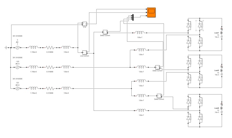
Voltage at transformer output:
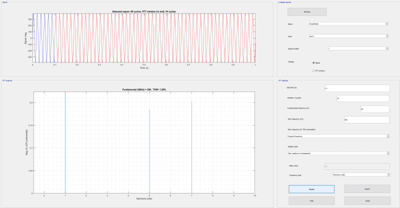
Current from transformer:
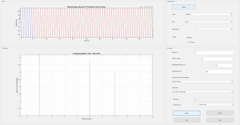
Current in the delta formed by the three rectifiers:
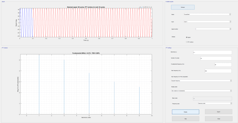
Edit: Sorry for the poor image quality; not sure what to do about that. Delta has 3rd harmonic and line does not.

Voltage at transformer output:

Current from transformer:

Current in the delta formed by the three rectifiers:

Edit: Sorry for the poor image quality; not sure what to do about that. Delta has 3rd harmonic and line does not.
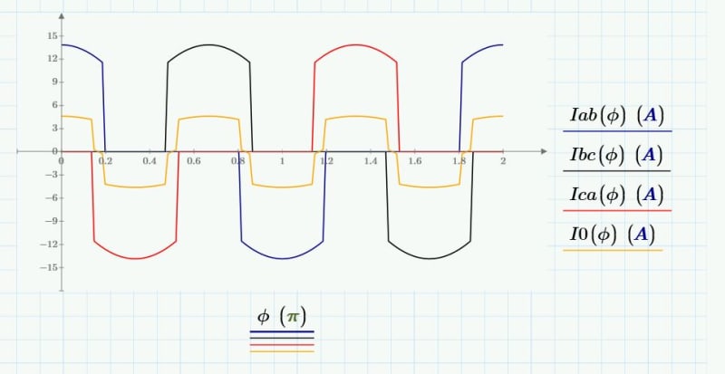
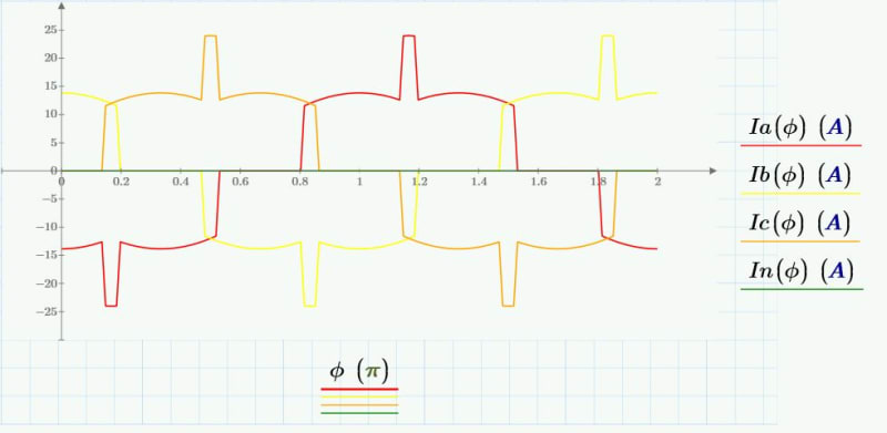
Good questions Jghrist. It would seem my effort to create a more realistic load failed. How about a half wave rectifier in series with a resistive load? Then the rectifier current and rectified current are the same. I0 is the zero sequence current circulating through the loads.
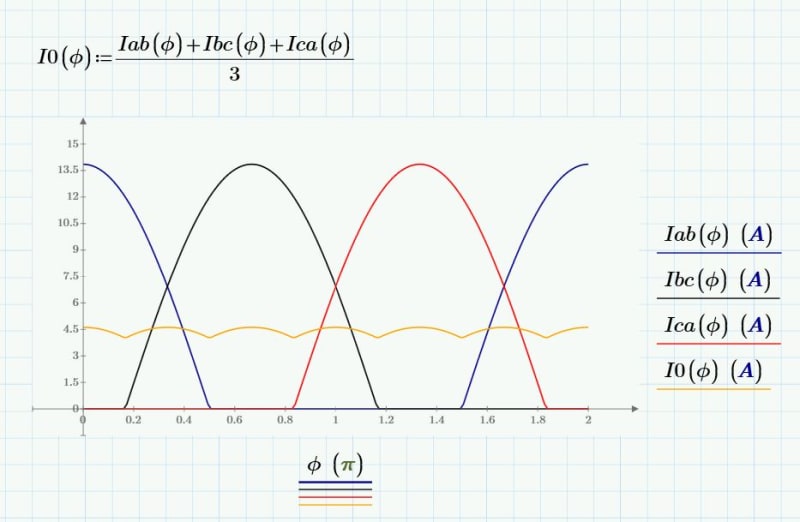
and:
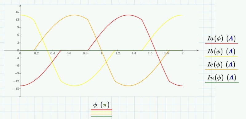

and:

I was considering the following from IEEE-519-1992:
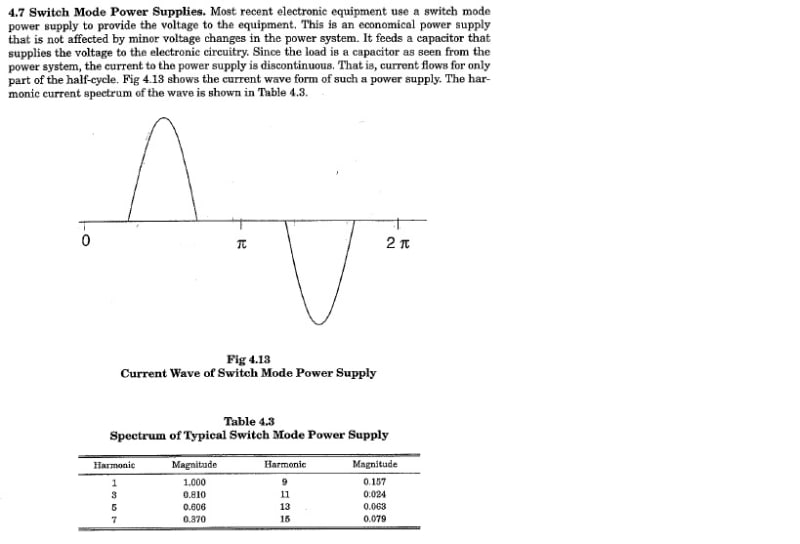
I would use this for Iab, shift 120 deg for Ibc and another 120 deg for Ica. Unfortunately, I am temporarily without Mathcad.
In a switch mode power supply, the current only flows during that part of a cycle when the voltage is above a certain amount.

I would use this for Iab, shift 120 deg for Ibc and another 120 deg for Ica. Unfortunately, I am temporarily without Mathcad.
In a switch mode power supply, the current only flows during that part of a cycle when the voltage is above a certain amount.
- Status
- Not open for further replies.
Similar threads
- Locked
- Question
- Replies
- 28
- Views
- 2K
- Locked
- Question
- Replies
- 12
- Views
- 1K
- Locked
- Question
- Replies
- 2
- Views
- 3K
- Question
- Replies
- 2
- Views
- 750
- Question
- Replies
- 13
- Views
- 15K

