Continue to Site

Eng-Tips is the largest engineering community on the Internet

Intelligent Work Forums for Engineering Professionals

  • Congratulations KootK on being selected by the Eng-Tips community for having the most helpful posts in the forums last week. Way to Go!

Nonsensical Stress Values - Internal Pressure and Temperature on Cylinder 7

Status
Not open for further replies.

mtz_engr

Aerospace
Jan 6, 2022
19
Hoping to find someone that knows a bit more than I do on this matter.

I currently have a cylindrical geometry modeled and meshed with 2D Quad elements. This has been assigned Titanium material properties and a specified thickness. I have several load cases of combinations of internal pressure values (100 to 6900 psi) applied to the internal faces of the elements and temperatures values (-400 to 1000 deg F) applied to the nodes of the mesh. Both ends are fixed in translation and rotation. (intial temperature set as 70 deg F)

I started by performing a Linear Static solution to see what kind of results I got. I am interested in the tangential stress around the cylinder, because this is the principal stress and what should be the highest for this geometry. Interestingly enough, towards either end of the pipe, the stress values are highly negative (I am talking 100,000+ ... Saw -430,000 psi on one case) and the largest value seen towards the center is around 35,000 psi for the extreme case of pressure and temperature.

Doing hand calculations of the tangential stress causes by pressure and temperature, I arrive at around 93,000 psi for the combination of the hoop stress and thermal stress. I designed the geometry in the model to be able to handle this with a modest factor of safety.

Can anyone give me any indication of why the values I am getting in FEA are so strange? (Nonsensically negative towards the ends and positive but low towards the center)

Thanks in advance.

Using Patran/Nastran 2020
 
Replies continue below

Recommended for you

You will get large (in terms of absolute value) stresses at the ends due to boundary conditions. Did you try solving this in plane strain or with solid elements ? Is the mesh sufficiently refined ?

Screenshots of the model could be useful to provide help.
 
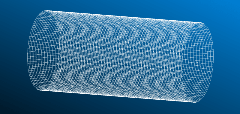
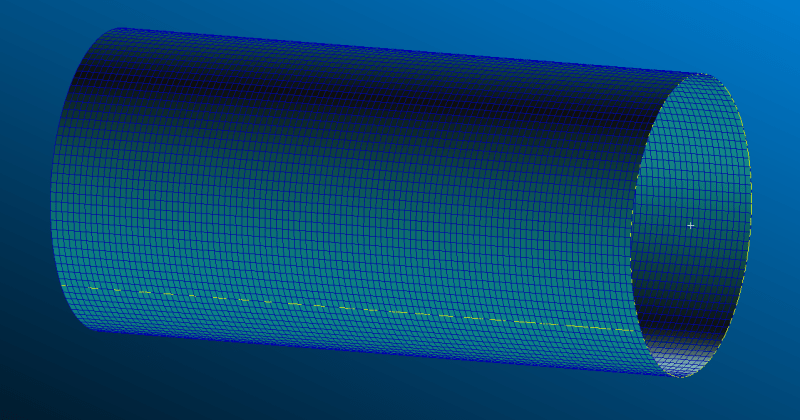
Sure thing! Attached just 2 snapshots of the model in wireframe and smooth shaded.

To elaborate, there are 100 elements down the length of the model and 100 elements that follow the circular path. So it ends up being 10,000 elements used.

I thought it was interesting that the von Mises stress it shows was much higher than the x-component (tangential direction). I also figured the stress would vary towards the ends due to the boundary conditions, but was confused to see what I thought would be a purely tensile load cause extremely large compression numbers towards the ends.

The elements used are 2D Shell elements. QUAD4 in particular.

model1_ma7nkx.png
model2_dutymq.png
 
That's a very fine mesh, no need to further increase its density. However, as I've mentioned, I would try with other types of finite elements. Maybe you will also be able to apply different boundary conditions that don't overstiffen the ends of the pipe. But this depends on the real-life support conditions.
 
Yes, the mesh is indeed pretty fine. It is set up that way because of the number of data points needed from the output of this analysis.

Thanks for the suggestion. I will experiment with some other elements. I have just read that 2D Shell elements tend to be quite good at idealization for thin-walled pressure vessel types of models.

I have thought about the boundary conditions a bit. For its use right now, the boundary conditions aren't rigidly defined. I think I have seen someone recommend only restraining a single point for an open-ended pressure vessel type problem.
 
Shells are indeed the right choice for thin-walled structures like that but in some cases they are insufficient.

You could also utilize symmetry in this model to solve it faster and to make boundary conditions less problematic (unless the loading is unsymmetric of course).
 
Update:

Tried this 3-2-1 method of constraining the model found in this forum that seemed to work for other people.

The stress found was uniform throughout and in a positive realistic value range.

The only issue now is that pressure seems to be governing how much the stress changes rather than temperature. What I mean by this is that changes in temperature seem to have little effect on the stress values seen in the results. This should not be the case, especially when there is temperature of 1000 deg F applied. The stress values I am getting now are too low. I have used a Coefficient of Thermal Expansion that handles units in Fahrenheit and have assigned Fahrenheit values to the temperature loads.

So, now I have to try and discern why that might be.
 
Double-check the input values and make sure that all units are correct, that’s often the cause of wrong results in such cases. What about the analytical solution - how does it compare to the values you get with temperature included ?

Thermal stresses are very sensitive to boundary conditions. Try the approach with symmetry, it might give you better results.
 
When you say symmetry, do you mean turning the 3D problem into a 2D one? Or just cutting the problem in half. I understand people take symmetrical geometries/loads and will sometimes cut them in half to reduce complexity of the problem.

Also, I have the pressures applied to the internal face of the element and the temperatures applied to the nodes. As far as I know, that is fine, but I could be wrong here.
 
Not necessarily 2D (although I would try plane strain too). You can utilize planar symmetry reducing the model even to one-eighth. You just have to apply symmetry boundary conditions to the edges or faces of the cut. Many FEA codes have predefined BCs for that, in others you have to manually select proper degrees of freedom. In 2D symmetry would also be helpful but you would have one direction less to worry about.

Yes, that’s correct - distributed loads are applied to the faces of the elements while temperatures are defined for nodes.

Check the reference temperature definition too, it’s important in thermal stress analyses.
 
The analytical solution is about an order of magnitude higher than the FEA results. Which makes me think there is an error with inputs. Alas, the inputs were double-checked and were correct.

Currently, I have the reference temperature and the initial temperature both set at 70 deg F. So, I expect it to expand plenty at the higher temperature values, but this does not seem like the case.

I see that I can set up the material properties as a 2D Solid for the plane strain responses. Going to try that and see what happens.

Thanks for your help!
 
You should not completely fix the ends of the column. If this is continuous pipe or connected to any other pipe by flanges or connected to equipment, making use of cylindrical co-ordinate system based boundary conditions would reduce the stresses. You need to fix only theta and axial translational degree of freedom and free the radial translation direction (for solid elements) as radially the pipe is free to move(Unless not completely blinded off or attached to stiff structure which would not allow radial movement). Still the stress values would be expected to be much higher due to the temperature and axial restraint provided at the end (Thermal stress). But I would not worry about those as these are secondary in nature and higher allowable stress can be used (See ASME Sec VIII Div 2)
 
Update:

Was going to try the plane strain, but tweaked a few more parameters and ran it with the 3-2-1 BC.

Stress induced by the pressure in the tangential direction (Hoop Stress) has a 0.05% error between theoretical versus FEA results. NICE!!!

Varying the temperature causes no change in the tangential direction stress. (i.e. 100 deg F and 1000 deg F cause the same amount of stress, which is likely calculated to be zero in the FEA, with an initial temperature of 70 deg F and reference temperature of 70 deg F)

So, does anyone know why a large temperature difference (such as 1000 degF from 70 degF) causes no stress in the model with a Coefficient of Thermal Expansion of around 5.11 microin/in-degF ?
 
As I've mentioned, thermal stress analysis results are particularly sensitive to boundary conditions. You have to make sure that they correspond to the assumptions of the analytical solution.

Can you share the complete data - all dimensions, material properties and prescribed values as well as the formula used for the analytical solution and the result of it ?
 
Ro: 0.233 in
Ri: 0.172 in

When constructing the geometry, averaged these to get the midplane radius and applied thickness in material properties.

R: 0.2025 in
L: 0.9320 in
t: Ro-Ri = 0.0610 in

Meshed with QUAD4 elements (100 around the circle, 100 down the length)

Material Properties of Ti-6Al-4v
E = 16500000 psi
Poisson = 0.33
Density = 5.14784 lbf/in^3
CTE = 5.11E-06 in/in-degF
Reference Temp = 70 degF

Load Cases (internal pressures on element face and temperatures on nodes)
P3500_T-400 P3500_T-330 P3500_T-260 P3500_T-190 P3500_T-120 P3500_T-50 P3500_T20 P3500_T90 P3500_T160 P3500_T230
P3500_T300 P3500_T370 P3500_T440 P3500_T510 P3500_T580 P3500_T650 P3500_T720 P3500_T790 P3500_T860 P3500_T930 P3500_T1000

P100_T300 P440_T300 P780_T300 P1120_T300 P1460_T300 P1800_T300 P2140_T300 P2480_T300 P2820_T300 P3160_T300
P3840_T300 P4180_T300 P4520_T300 P4860_T300 P5200_T300 P5540_T300 P5880_T300 P6220_T300 P6560_T300 P6900_T300

Quite a few load cases... held T constant and varied P. held P constant and varied T.

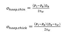
Formula for checking pressure induced tangential stress (Hoop Stress)
hoopeq_h1rjo6.jpg

@ 6900 psi P_i
hoop thick = 26355 psi
hoop thin = 22906 psi

(FEA shows stress for this as 22894 psi)
hoop thick ~ 13% error
hoop thin ~ 0.05% error

This tells me the FEA arrives at the same answer as the thin-walled result.

Formula for checking temperature induced tangential stress
thermaleq_ilcjkf.jpg

@ 1000 deg F and 70 deg F
thermal stress = 67270 psi

FEA essentially says this is zero. (i.e. same pressure but different temperatures give the same stress)
 
Your input data looks correct. However, the key here is to clarify which variant of boundary conditions you assume. Do you want to allow the pipe to freely expand in the axial direction or should it be fully restrained at both ends ? This will determine what thermal stresses you get as a result and what analytical solution you should use. Is the purpose of this analysis to simulate the behavior of a real structure or is it just a theoretical consideration ? What is the source of the analytical formula you are using - does it come from some book ?
 
If there is no restraint on the pipe, and the temperature field is uniform there will be thermal strain, but zero thermal stress.
 
I added the 3-2-1 method of constraints on both of the ends. This works out to 6 constrained points.

The stresses vary through the length of the pipe like you would expect. However, the stresses are still not as high as I calculated.

Thanks SWComposites, I see that now as I have played with it a bit more.

FEA way, I suppose that is where my issue lies. I thought it would be simple to completely fix both sides because I have no specific boundary conditions yet, but I know that the minimal constraints are not sufficient for the thermal aspect of the problem.
I quickly worked out the thermal stress formula from the only source I could find. This gives a integral equation for it, but I worked it out to be something similar to what I posted previously. What are your thoughts?

Thanks for the prompt responses.
 
The 3-2-1 method is interesting but one has to keep in mind that it's meant for situations when you want the model to be rather "free-floating" and relying on the load balance itself but the software requires some constraints to eliminate rigid body motions.

For the thermal stresses to develop there must be some constraints (internal or external). It can be a fixed constraint on both ends (external constraint), a connection of materials with different thermomechanical properties or simply a temperature gradient. The analytical formula that you use assumes the latter cause of thermal stresses since it's meant for nuclear reactor pressure vessels. If you look at the boundary conditions described there, the following assumptions are made:
- inside surface - convective heat transfer with hot water flowing in the pipe
- outside surface - zero heat flux (insulated)
 
mtz_engr

NRP99 said:
You should not completely fix the ends of the column.

Read "pipe" instead of "column". I am still not seeing any problem unless the boundary conditions are completely wrong. Perhaps a screenshot of stress results/boundary conditions would help to understand what is going wrong here. Or Perhaps little bit more background information is what I need to make proper suggestion like what part is this? How its exposed to this much temperature and with what medium? How the ends are restrained? etc. etc.

What I stated about boundary conditions and stress evaluation in my earlier post is normal way of solving the problems in Pressure vessel industry. If this is applicable to you, it should solve your problem.

D/t ratio is (0.344/0.061)=5.63<20 means you cannot approximate to thin shell approximation or shell modelling approach. It is ok but 3d solid modelling will give somewhat better accuracy as its thick shell.
 
Status
Not open for further replies.

Part and Inventory Search

Sponsor