Eng-Tips is the largest engineering community on the Internet

Intelligent Work Forums for Engineering Professionals

Nonsensical Stress Values - Internal Pressure and Temperature on Cylinder 7

Status
Not open for further replies.

mtz_engr

Aerospace
Jan 6, 2022
19
0
0
US
Hoping to find someone that knows a bit more than I do on this matter.

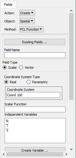
I currently have a cylindrical geometry modeled and meshed with 2D Quad elements. This has been assigned Titanium material properties and a specified thickness. I have several load cases of combinations of internal pressure values (100 to 6900 psi) applied to the internal faces of the elements and temperatures values (-400 to 1000 deg F) applied to the nodes of the mesh. Both ends are fixed in translation and rotation. (intial temperature set as 70 deg F)

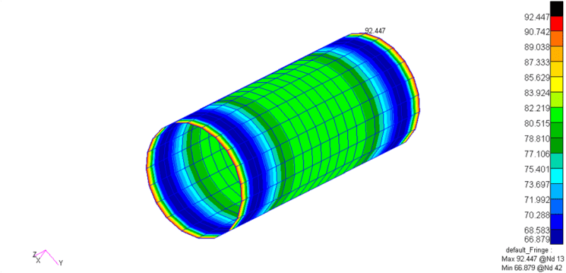
I started by performing a Linear Static solution to see what kind of results I got. I am interested in the tangential stress around the cylinder, because this is the principal stress and what should be the highest for this geometry. Interestingly enough, towards either end of the pipe, the stress values are highly negative (I am talking 100,000+ ... Saw -430,000 psi on one case) and the largest value seen towards the center is around 35,000 psi for the extreme case of pressure and temperature.

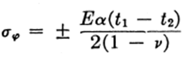
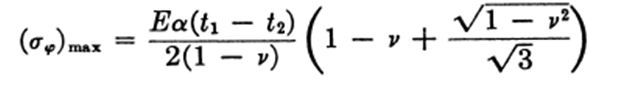
Doing hand calculations of the tangential stress causes by pressure and temperature, I arrive at around 93,000 psi for the combination of the hoop stress and thermal stress. I designed the geometry in the model to be able to handle this with a modest factor of safety.

Can anyone give me any indication of why the values I am getting in FEA are so strange? (Nonsensically negative towards the ends and positive but low towards the center)

Thanks in advance.

Using Patran/Nastran 2020
 
Replies continue below

Recommended for you

This is supposed to be a generic component used in liquid rocket engines. The pressure and temperature data is taken from one engine in particular as an example of loading environment. These temperatures are given to be what temperature the inner wall experiences after heat transfer has been considered from the moving fluid. I am trying to solve a generic case that would be formulated early in the design and use that many load cases as a means of forming a stress distribution from the data.

The problem with it being a generic case is that the boundary conditions aren't explicitly decided yet, which I understand will definitely affect the stress. The idea here is to determine what the distribution of the stress would look like at this range of loads when the component has been designed based on the analytical results + a factor of safety consideration.

I am struggling to determine what boundary conditions would work for my problem. If it is constrained too much, there are issues. If it is constrained to little, there are issues.

I will try the 3D solid modeling approach, but I still believe you both are correct in suggesting the boundary conditions are the real issue here.
 
The equation that the OP has posted for the thermal stresses in the hoop direction are derived with the assumption that there is a temperature gradient through the wall thickness of the cylinder. Your FEA does not model that. You have a zero gradient (constant temperature) across the shell thickness and you use rigid-body constraints (free-free ends) so naturally you get zero thermal stresses.

Try modeling the temperature gradient through the shell thickness with rigid-body constraints applied. This should model your problem based on the theoretical formulas you have provided.
 
Okay! I took a stab at your problem. I've taken the case where:

p = 6900 psi
Ti = 1000 degF (on the inner surface of the cylinder)
To = Tref = 70 degF (on the outer surface of the cylinder)

For a temperature gradient in the radial direction, assume that Ti and To are the uniform temperatures at the inside and outside cylinder surfaces respectively, and the temperature variation across the wall thickness is linear. The stresses in the hoop direction at the outer surface of the cylinder away from the edges are taken from Timoshenko’s text on Plates & Shells as:

image_2022-01-09_191720_y8dtem.png


The symbols have their usual meaning. Here t1 = Ti and t2 = To. Hand clac’ed values are:

Shoop(thermal) = 59 ksi

Now using the thermal stress formula which the OP had quoted earlier and with the values provided, I get:

Shoop(thermal) = 64 ksi

So, its comparable with what Timoshenko gives.

The max thermal stresses will be on the outer surface in the hoop direction at the free-edges given once again from Timoshenko’s text as:

image_2022-01-09_191920_xzw0g6.png


Hand-calc’ed values are:

Shoop(max_thermal) = 71 ksi

When these results are superimposed over the pressure case, we have:

Shoop(total) = Shoop(max_thermal) + Shoop(pressure) = 71 + (6900*0.2025/0.061) = 94 ksi

The location of the max stress is at the free-edge.

Modelled the cylinder using CQUAD4 shell elements using MSC.Nastran. Made a coarse mesh of just 20 elements across the length and circumference. Defined the temperature variation across the thickness of the cylinder using the TEMPP1 card. An internal pressure of 6900 psi is applied using the PLOAD4 card. Used the same dimensions and material properties as the OP has quoted before. Boundary used are free-free at the ends and just the rigid-body modes suppressed. Ran it for the combined pressure + thermal case.

Compared with FEA:

Shoop(total) = 94 ksi (Theory)
Shoop(total) = 93 ksi (FEA)

Below is the stress plot from the FEA showing the hoop stress on the cylinder outer surface.

image_2022-01-09_192118_bvasqe.png
 
@nlgyro

That is fantastic! A few follow ups.

I was wondering how to consider Thermal Stress as a function of the geometry (Ro, Ri). That is how I found the original equation I used. I suppose it is not 100% necessary as the results you obtained and the theory line up quite nicely.

Can I ask how exactly you constrained the model? You said Free-Free ends with Rigid Body Motion prevented. So does this mean you constrained the z-direction and all rotations?

Also, I can't find any resources for how to apply the TEMPP1 information (i.e. the linear gradient) to my model in Patran. Would you be willing to explain it or point me in the direction of good resource?

Thank you and great work!


Well... this is pretty easy to do if you’re modeling your problem as a 2D plane strain or as a 3D model.

To consider the thermal stresses as a function of geometry you must create the nodal temperatures as a function of the geometry (radius in this case)

Let us assume a linear variation of temperature across the wall thickness of the cylinder of the form:

T = To + (Ro-r)/(Ro-Ri) *(Ti-To)

where:
T = Temperature at a given radial distance 'r'
Ti = Temperature at the inner wall
To = Temperature at the outer wall
Ro = Outer radius
Ri = Inner radius
r = given radial distance.

You can use the Create--> Spatial---> PCL Function option in the 'Fields' menu of Patran to enter this equation. The FE-model needs to have all the nodes associated to a radial co-ordinate system for Patran to pick up the radial distance of a given node in your model.

Fields_Menu_k9u9o3.png


So, give a name for your field under "Field Name"
Use the Field Type as "Scalar"
Co-ordinate system type as "Real"
Under co-ordinate system select the radial co-ordinate system that you have created. (The coord 100 that you see is the radial co-ordinate system that I had created.)
Now considering the temp and geometric values in your example the equation in Patran would be entered as:
70 + (0.233-'R)/ (0.233-0.172) *(1000-70)
under "Scalar Function". 'R is the Patran convention for the nodal radial distance.

Now in the Loads menu under Create--> Temperature ---> Nodal under "Input data" select the above created field in the 'temperature' box. Click on the "Select Application Region" and select all the nodes in the model. Hit Apply for patran to interpolate the nodal temperatures. Once you run the model you'll have the variation of thermal stresses across the thickness.

Now the model that I did was a plane-stress model using 4-noded shell elements. The temperature interpolation across the shell thickness was done using Create--> Temperature ---> Element Variable. In the input data you just enter the top and the bottom surface temperatures which would be To and Ti respectively. In the Select Application Region, just select all the shell elements. This automatically creates the TEMPP1 card which contains the parameters for Nastran to do a linear interpolation across the shell thickness. Refer the nastran quick reference guide for more details on the parameters of the TEMPP1 card.


There is a standard way to do this when modeling cylinders/pressure vessels. Follow the slides in the attached pdf.

[URL unfurl="true"]https://res.cloudinary.com/engineering-com/image/upload/v1641894801/tips/RBE3_Example_ojmo50.pdf[/url]


Explained above. General rule... for description on all nastran cards use the nastran quick reference guide which is available in the nastran documentation folder along with the software installed on your PC. Version of the quick reference guide are also available online in the MSC website.

From the load-cases that you have posted earlier looks like you are dealing with super cold and super hot fluid conditions. This means at some stage in your analysis your mechanical properties such as E, G, nu and alpha would have to be considered as functions of temperature. The MATT1 card in nastran comes in handy for this.

Good Luck!
 
Good nlgyro.

nlgyro said:
There is a standard way to do this when modeling cylinders/pressure vessels. Follow the slides in the attached pdf.

I would recommend to use datum cylindrical coordinate system and apply theta and axial constraint at the ends directly as stated in my first post rather than doing whole RBE3 exercise.
 
Interesting slideshow on RBEs. I am not sure I fully understand what it is saying though.

It looks like it is saying make 3 nodes the independent terms in an RBE for all 6 DOF, then, for every other node, make it the dependent term for those three independent terms in all 6 DOF.

That must not be the case, because I just tried it and received an error.

Could I not just constrain the entire side in rotation and axial directions to achieve a similar result? Or does that add stiffness to the model.
 
Hi everyone,
I design reactor with partition plate divided the reactor to two separate reactor. one side the design temperature is 350 centigrade degree with 3.5 bar internal pressure. the other side is empty and under ambient temperature. I want to design the partition plate but under this gradient temperature the stress is two high in the place of contact the plate with shell. I use FEA with ANSYS . the stress is 4000 MPa. I model the partition plate and a part of shell with internal pressure and convection for thermal. I think my model has a problem that the stress is two high. when the stress linearization based on ASME sec viii part 5 in not pass. Could you please give me a advise?


If you look at slide 44 that's all you need! Just one wagon-wheel RBE3 at one end of the cylinder which connects the dependent node at the center to the independent nodes on the circumference. Use dof's 123456 for the dependent node and 123 for the independent node. Select 3-nodes 120degs apart on the circumference and add them in the UM nodes putting theta and Z dof's in the UM set. Add a SPC 123456 at the dependent node at the center. This method constrains all rigid-body modes and allows for un-constrained motion when you have self-equilibrating mechanical loads and thermal loads (such as an aircraft in flight) without constraining the model to ground. This is a generic way of doing it.


@miningman

A lot of posters here tried to support the OP's question in a professional manner by spending their time in understanding what the OP is trying to doing with an intention of helping him out the best they can. None of them have taken cheap-shots! Why do you undermine the efforts of such people by labelling this exercise as GIGO?? Being your first post on this forum all that you have done is just post your typical arm-chair rocking/pipe-smoking condescending BS!! What a retard!!

Is it just me or should the moderator of this forum (if there is one) step-in to reign in these "Kids these days... Ho! Ho! Ho!" types??? I'm sure the internet is full of free un-regulated spaces where such BS flies!!
 
Thanks @Couch_King

If I knew everything, I wouldn't be here. Was fortunate enough to have some good folks that know this topic better than I do share their advice.

Very thankful to the people who share their knowledge here!
 
@nlgyro

So, the best I can understand this is to set up the center (20000) as a dependent node in 123456. Then add every point on the circumference to the independent set in 123. Then, to achieve a similar looking RBE3, add the three separate points that are 120deg apart to the dependent set in 36 (translation in Z and rotation in Z with Z being along the axial direction).

The center node has a SPC 123456 and it is the only SPC specified.

Does this sound right to you? Because I still seem to be getting errors once I submit the job to Nastran and check the F06 file.

rbe3_1_psmp4d.png

rbe3_2_lojca5.png
 
Couch_King

I do not want to be rude but you made the same mistake of posting your first post with only rant not showing professionalism either. You can help forum without using derogatory words. I, to some extent, agree to the comment by miningman since lot of questions are based on input provided by analyst to software and not able to understand the software output they got. That suggest something, right?

mtz_engr

I would suggest to look at previous responses one more time. It seems you are trying hard in implementing the software procedure and without understanding the physical understanding of the problem. This would be not be helpful to you if you avoid understanding the problem physics before you try to solve in analysis software. Then you will get bounced by these sort of questions/errors every time you analyze any complicated problems.


Seriously!! You have this poster miningman(Mining) whose first post on this forum (before the comments were deleted) demeans and take cheap-shots at the efforts of the posters who have tried to help the OP with his problem by labeling the entire exercise as GIGO without contributing one useful bit to the discussion. Now this is derogatory and lacks professionalism. Plain and simple. It’s akin to making fun of someone who fallen into a swamp for having fallen into the swamp!! The least you can do is the help him out and then point out his mistakes. That’s decency. All I did is point this out in no uncertain terms.


Well I don't want to sound rude either, but the introspection should start with some of the gems that you have belted out on this discussion.

Now this is a free site. If you are an experienced FEA user, you are welcome to stop-by and help other if you have the time and the willingness to do so. Otherwise you’re free to move on but don’t turn it into swamp just because some user asks a question too pedestrian or lacks the understanding of the problem he is trying to solve. People like me who use FEA very rarely stop-by at this forum just to pick-up tips and tricks from experienced users. The last thing we want is for the experienced users to flee this forum or to lose interest in posting anything because there is always some random user/users who contribute nothing but makes it a point to stop-by just take cheap-shots at other users who genuinely help the OP with his/her FEA problem!! I think the response by the OP underscores my point:


I sincerely feel this discussion forum could be better moderated!!
 
How odd. I reconfigured the RBE3 to have the 23 DOF for the three nodes, but there is still an error.

In the F06 file, the OLOAD RESULTANT matrices for each subcase has approximate zeroes everywhere.

However, there are two sections with error messages. One concerning the UM set. The other concerning the matrices. (Attached photos for F06 text)

It seems like a DoF in the RBE3 is dependent on itself in some way. Thinking this could be a problem with the three 23 DOF nodes being in the dependent and independent sections?

Seems weird that I would receive this error if you are not and are performing this same operation.

f06_1_fiunle.png

f06_2_dpzpd4.png
 
Ah. Well, after playing around with the coordinate system, I found that there were issues with the nodes RCID versus the ACID.

So, now I have achieved a similar functioning model to yours. I changed the geometry based on the Timoshenko equation during design.

At the Max P and Max T,

Hoop(total) = 86.3 ksi (FEA)
Hoop(total) = 93.6 ksi (Theory - Hoop thick formulation)
Hoop(total) = 90.1 ksi (Theory - Hoop thin formulation)

Mind you that based on the new geometry the theoretical formulation should be for thick version of the equation.

Based on that, we have around an ~8% difference. Wondering where that difference is coming from. I know the FEA isn't perfect, but would like to know how to account for that.
 
Questions

- where are these stresses measured? Outer/inner & middle/ends of the pipe??

- what are these new dimensions??

- same max pressure and max delta-temp as earlier??
 
Because I have modeled it as a 2D surface, I believe it is measuring it at the midplane (Ro-Ri)/2. I modeled it at the midplane because when you apply thickness to the material properties, it extends out in both directions (from what I have read).

I believe this is the source of error, because the FEA may be outputting the midplane values, while the theoretical results output the maximum value that is experienced at Ro.

Also, the maximum values in the FEA are on the ends, so that is the value being compared to theory.

New dimensions are 0.212 in and 0.133 in for Ro and Ri, respectively.
The midplane value that the geometry in FEA is created from is 0.1725 in.

Temp and Pressure values are still the same, yes.
 
Status
Not open for further replies.
Back
Top