Continue to Site

Eng-Tips is the largest engineering community on the Internet

Intelligent Work Forums for Engineering Professionals

  • Congratulations KootK on being selected by the Eng-Tips community for having the most helpful posts in the forums last week. Way to Go!

Notched LVL 1

Status
Not open for further replies.

XR250

Structural
Jan 30, 2013
5,409
Here is my situation in an as-built condition...
LVL_joqdub.png


If I model it as a 24"/16"/24" beam, the numbers work out for strength and deflection while ignoring the column. I want to ignore the column as it will be easier than trying to fix the sketchy load path. I will likely have the contractor remove it. Is there any thing to fix here?
The notching guide for LVL's allows a top notch of 0.4D max over 1/3 the span but it only addresses notches that start at the bearing. I feel like I am OK here though.
 
Replies continue below

Recommended for you

Personally, I'd reinforce it with at least a partial length 16" LVL at the notch even if the numbers workout without it.

You can call Weyerhauser technical support and they can evaluate these conditions for you. Or at least they used to.

I believe for a compression side notch they would recommend you apply a stress concentration factor of dn/d to the moment and shear capacity. If the column remains you'd probably want to consider it a tension side notch which I believe they would recommend (dn/d)^2 as the stress concentration factor.
 
I'd be concerned about stress concentrations around the notch corners. If there's room to make the beam wider, it may be prudent to add a partial length 24" LVL on each side of the existing beam.
 
JDG said:
I believe for a compression side notch they would recommend you apply a stress concentration factor of dn/d to the moment and shear capacity. If the column remains you'd probably want to consider it a tension side notch which I believe they would recommend (dn/d)^2 as the stress concentration factor.

Where are you finding this in literature? FWIW, the beam cannot be reinforced without a huge amount of effort. It does not pass assuming it is just a 3 ply 16" the entire length due to deflection. Without the column, I am getting 2,400 PSI fb. With the column it reduces to 400 PSI.
 
Since LVLs are manufactured to have nearly perfect horizontal, parallel grain, the risk of splitting at the corners is pretty high. Getting a flat tire repaired so I can't dig the pdf out, but New Zealand has some top notch guidance on this topic. If you can't find it, I'll share later.

My preference for a notch that big would be a high grade, thick plywood glued and screwed to the side. For smaller notches I like long, skinny screws, but you'd have trouble with that here.
 
APA G535 recommends compression side notches should only be made in areas of the beam stressed less than 50% of the allowable bending stress, and that the resulting net section be checked for shear and bending.

They also recommend radiused corners at the notch to reduce stress concentrations and splitting risk.


I think removing the post to put the notched section on the compression side is a good idea, but my concern would be increased deflection causing serviceability problems at the door. If pham's plywood reinforcement could be installed before removing the post, obviously that would minimize the deflections.
 
Bones206 said:
APA G535 recommends compression side notches should only be made in areas of the beam stressed less than 50% of the allowable bending stress, and that the resulting net section be checked for shear and bending.

Good to know. I am at 2,400 PSI so that does not work. Looks like I need to make the column load path work. Again, the beam cannot be reinforced at this time.
Thanks for everyone's help.
 
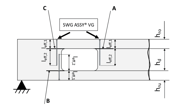
That APA doc also strongly discourages any tension side notches, except at end bearings. Maybe you could add those long screws down the top on each side of the notch to reinforce the splitting plane. Not sure if that was what pham was suggesting, but I pictured something like this (from this white paper:
Screenshot_2023-09-22_095620_gjxjrf.png
 
Maybe use long wood screws from above which would pass through the potential splitting planes, like:
door_notch_lz1agf.jpg

I would start the screws something like a ratio of 2:1 relative to the notch depth from the edge, so about 16" in your case. I don't know the best way to calculate the splitting force on the screws without thinking about it more, but there must be a way.

Also, if it's possible to provide a slight radius at the notch ends rather than a perfectly square cut with a sharp edge, that might help. I suppose that's not possible if this is as-built.

EDIT: Basically what Bones posted 5 minutes before me.
 
Yea, great sketch. That’s exactly what I envisioned. That white paper has design procedures for this kind of thing.
 
Status
Not open for further replies.

Part and Inventory Search

Sponsor