Tek-Tips is the largest IT community on the Internet today!

Members share and learn making Tek-Tips Forums the best source of peer-reviewed technical information on the Internet!

  • Congratulations cowski on being selected by the Eng-Tips community for having the most helpful posts in the forums last week. Way to Go!

NX 9.0 - Matching the contours of a solid

Status
Not open for further replies.

_MechEng95

Mechanical
Joined
Feb 28, 2017
Messages
22
Location
FR
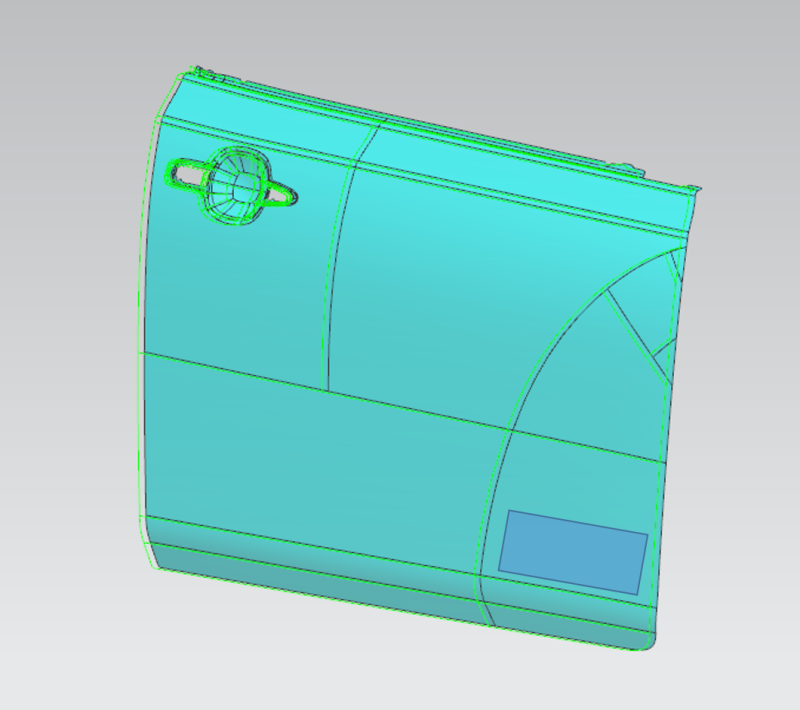
I am wondering what the best process for matching the contours of a surface in order to produce a setting jig are. Something like a badge on a car door for example.

I was thinking:
- Create a plane perpendicular to the farthest point of the surface.
- Sketch on the plane. Extrude to surface.

Is it that simple? Thats working with the part front on.

Would working with it in side view make more sense?
- Produce sketch on side view of part,
- Offset entities, (producing a sketch of the door edge)
- Offset the sketch by x milimetres (however thick I want the jig)
- Extrude and sketch on the extrusion.

Either method would match the contours of a door right?


I think i need an image illustration on what it is you have and want to do.

You are in the process of designing / manufacturing a setting Jig ?

Regards,
Tomas

Regards
Tomas
 
I am in the process of designing a setting jig yes.

Can't share photos. For example, I need to match a badge/logo to the back of a chair, the back of this chair is curved and the badge must be fit against the headrest.

All parts are referenced from the front centre of the seat.

How do I go about replicating the curve of the chair/headrest and how do I adjust the position of the badge to sit flush against the chair if it is referenced as I just explained.

Hopefully that makes sense.
 
extract and untrim the face and use it to Trim the new body of badge.
 
Picture1141_xnqase.png


So I have a body of a door. The blue shaded area is where a badge should be. I need to replicate the curves of the door, and produce a setting jig for the badge x mm from the side and y mm from the bottom.

I tried untrimming but really not sure. Any help apreciated.
 
Not sure I really understand what you're trying to do, but I would create a new part in the assembly, wave link in the face and use that as the basis for my "badge".
 
Status
Not open for further replies.

Part and Inventory Search

Sponsor

Back
Top