Continue to Site

Eng-Tips is the largest engineering community on the Internet

Intelligent Work Forums for Engineering Professionals

  • Congratulations GregLocock on being selected by the Eng-Tips community for having the most helpful posts in the forums last week. Way to Go!

NX CAM, engraving text on uneven surface, no extrusion in part, just text as constraint 1

Status
Not open for further replies.

paperappl

Industrial
Feb 18, 2019
7
Hi guys,

i want to engrave some text on uneven surface. I was able to create op with single lined text and outlined text (fixed contour op + text on a surface).
What i want is to engrave whole letters like a pocket but just with text on a surface as a constraint (no extrusion), look at the picture below for further details.
What would be the right way to do this?

We are just starting to use CAM at our company so I'm fairly new to CAM. (NX10.0.3.5 with NX13420N + Teamcenter 11.2.3)
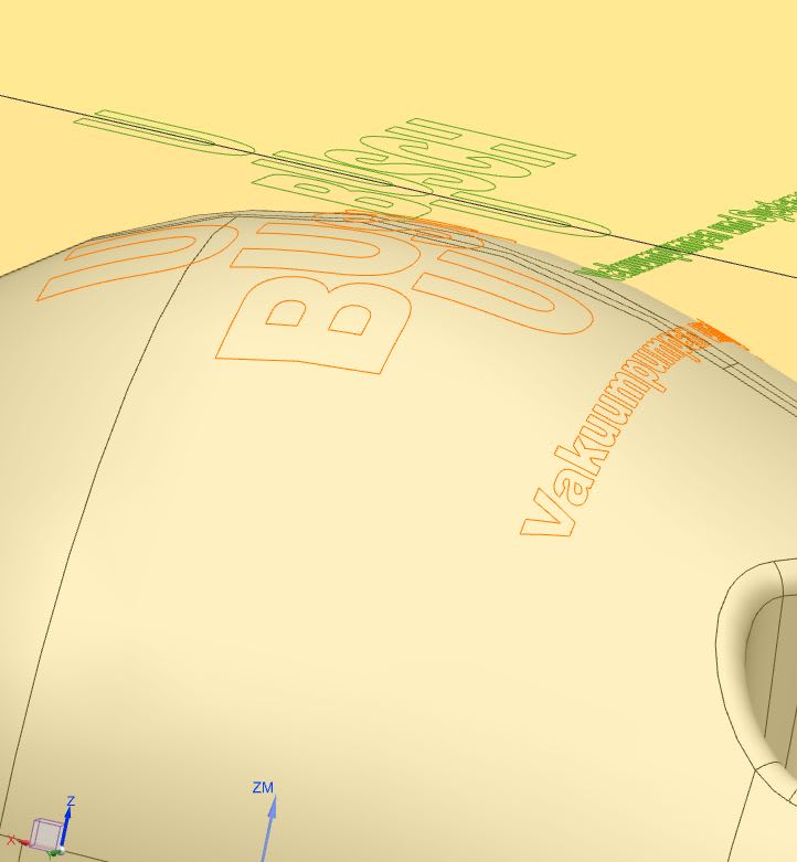
Engraving_on_uneven_surface_ngoza6.jpg


Thanks in advance!
 
Replies continue below

Recommended for you

It sounds like you successfully used a Contour Text operation for single stroke lettering but I think it only supports single stroke letters. It would be so nice to be able to pocket in 2D and 3D text operations but that's a seperate discussion for an ER, lol.

For pocketed letters I think you might have to use a Fixed Contour operation with Boundary for the drive method and Follow Periphery for the cut pattern. When you set negative part stock for the depth you can get an error if the negative stock amount is more than the tool radius, which is expected. If you run into that you can create an offset face for the path floor. It would be so nice to do this in one shot using the engraving operations but in the mean time you can do it this way.

If you are using a tapered cutter on your spherical surface you should project the geometry onto the face because boundaries are aware of tool taper.


Just remember to NOT divide by zero and the universe will be just fine.
[wink]

NX 12.0.2
EAP's
 
Thanks Tingsryd, it worked.

The thing with offset faces: how do you set it up exactly?
I tried to select offset face as cut area (part stock is set to 0) but
engraving path is still on surface and not below it.
What am i doing wrong?

Summary for embossed engraving:
op: fixed contour
drive method: boundary
drive geometry:
mode - curves/edges,
type - closed,
plane - automatic,
material side - outside,
tool Position - tanto.
curve rule - connected curves.
select each letter as separate boundary.
Drive Settings: cut pattern - follow periphery
Cutting Parameters: part stock: -0.2mm
 
@paperappl
Sorry, I should have said Offset Surface! This is a quick and basic method by the way and you do not need to do this unless you are using a negative stock amount which is greater than the corner radius of your tool. Such as -.8mm engraving depth and using a 1mm ball em. .8mm>.5mm( half the ball dia)

Create an Offset Surface (not Offset Face, that will alter your model) using a negative amount of whatever you want the engraving depth to be. This new surface is associative with the solid it was created from even though there is no check box for it. Select it for part and use zero stock.

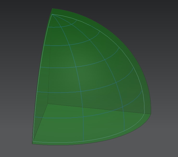
Here is a 1/8 section of a sphere with a negative offset surface. I turned on UV curves for clarity.
Image_1_tw3vpv.jpg


You can certainly model the engraving into your part but that can sometimes be a bit more work to program whereas boundary projected paths are a no-brainer and quick to program. If you do a lot of this engraving, and need to make realistic drafting prints, you might want to start experimenting with modeling the engraving into your part. What I have found when doing that is the results come down to the size and depth of the engraving verses the cutter size.

I hope this helps and be sure to post back with your results and if you have more questions!

NX 12.0.2
EAP's
 
Thanks again, Tingsryd!
So far so good, only one Thing: if i select original text on a plane as a constraint then the tool path is Looking good.
But when i select projected text then i either get really wired looking tool path or there is no tool path at all and no error either.
What's the deal with that? Is that normal behaviour?

NX 10.0.3.5 (NX13420N)
TC 11.2.3
 
I figured it out: when selecting projected text one should select a plane where it was projected from (user defined), don't leave it on "automatic".

Upd. summary for embossed engraving:
op: fixed contour
drive method: boundary
drive geometry:
> mode - curves/edges,
> type - closed,
> plane - automatic (if selecting original planar text) or user defined (if selecting projected text)
> material side - outside,
> tool Position - tanto.
Select each letter as separate boundary (curve rule - connected curves).
Drive Settings: cut pattern - follow periphery

Engraving depth:
1) Either with Cutting Parameters - part stock - negative value is the engraving depth.
2) or with Offset surface selected as a part. Offset value is the engraving depth.

NX 10.0.3.5 (NX13420N)
TC 11.2.3
 
Yes, boundaries should be on planes.

One last thing, are you using a straight or tapered cutter? In a situation like this tapered cutters complicate it a little.

NX 12.0.2
EAP's
 
Status
Not open for further replies.

Part and Inventory Search

Sponsor