Eng-Tips is the largest engineering community on the Internet

Intelligent Work Forums for Engineering Professionals

  • Congratulations waross on being selected by the Tek-Tips community for having the most helpful posts in the forums last week. Way to Go!

NX1872 - Exporting Step files...

Status
Not open for further replies.

DerkMc

Industrial
Apr 5, 2018
17
0
0
US
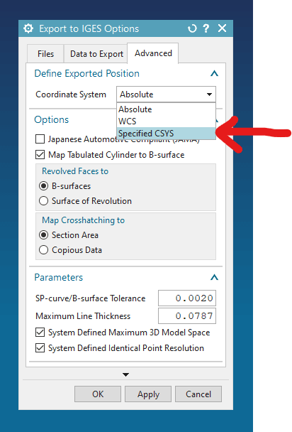
Long story short, we use NX11 primarily and have some custom functions setup. One said function writes out IGES, STEP and X_T files with just a couple clicks. One of those clicks is selecting the coordinate system we want to use. IGES and STEP export to the selected coordinate system and X_T does not.

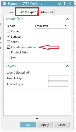
We have a customer that has started sending us files in NX1872. Our custom functions haven't been updated to work in NX1872 so I'm having to export each file type out one at a time...but STEP does not give me the option to select a coordinate system. It only writes out to the WCS location. Short of exporting an IGES, importing said IGES, and exporting back out as a STEP, is there a way to write a STEP out to any coordinate system in a part?

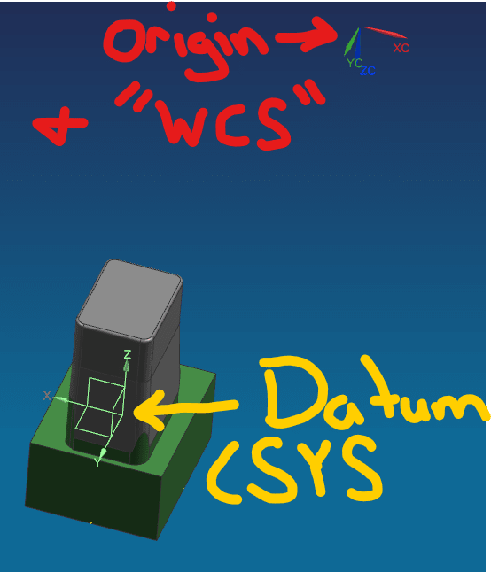
Also, I can't (not that I can't, but that's not the way we do it, plus I would have to create an additional file) move the model so that the needed coordinate system and the WCS would be the same...unless that's the least complicated way.

I appreciate the help and hope I'm just overlooking something simple.
 
Replies continue below

Recommended for you

Capture_i18ch9.jpg


Jerry J.
UGV5-NX1884
 
Cowski, I can't. It's controlled by another group and I don't have access.

Jerry, that just exports the model with the datum coordinate system in the export, it doesn't make the datum csys the 0,0,0 (origin) of the newly exported file.


To give an example of what I'm wanting to do, when I export a STEP it automatically exports with the origin as 0,0,0 (shown by the visual of the WCS). But I'm wanting to export the 3D shown with a 0,0,0 at the same place at the datum csys (marked with yellow). I can do this with IGES files (shown in the second image below).

image_gqjeoh.png


image_gzfxta.png
 
Don't know if the last sentence ( "...additional file...") means having a "export assembly" or not.
our scenario is that we have different "areas" in a large "site". Each area is modeled around a local coordinate system and later the area is placed/ positioned in the "site" assembly.( imagine area A, B, C etc in a factory building)
when exporting to step, we use arrangements to suppress all areas except "A" in the "site", then export the "site" but name the exported step file "A.stp".
this way "A" will have the position stored in "site" in the step file.

Regards,
Tomas


Toost, I believe we are talking about the same thing when you say "export assembly" and I said an "additional file".

We usually have three files per part.
-File "A" is where we design the part (we will call it "XX" in this example). Depending on how far part XX is away in the main assembly, it could be a couple feet from the origin in file "A".
-We then create file "B" that references file "A". In file "B" we move the referenced part (XX) to the origin of the file and detail part XX.
-Then we create file "C" that references file "B". In file "C" we export part XX for others to use. In file "C" we sometimes create additional models that reference the original part (XX). These additional models may be several inches away from the origin (like the picture shown in a previous post). In NX11, we had an icon (customized feature/program) that would allow me to select the created Datum CSYS of these additional models and it would export them as IGES and STEP files with that created Datum CSYS as their origin.

But with NX1872, it looks like I'm going to have to create a 4th file so I can move these additional models to the origin so I can export them individually with the needed origins. That is until the other division has time to update these custom features/programs to work with NX1872.

I'm curious if anyone knows why IGES lets you select "Absolute", "WCS", and "Specified" coordinate systems, but STEP and parasolid do not.
 
Hm,
unless Your custom programs dictate the setup, i think you should try "my method" which i tried to describe in previous post. ( 2 files, one for the geometry and one for positional control.)
I see no reason for your "B" part, it should be possible to go direct from "XX" to "C" ?
and no reason that NX1872 should change that ?

Iges is a VERY old format by today, the last change was 1996. (!)
( This does not mean that it cannot be used if it delivers what one expects, but it will not be enhanced in the future.)

Why the step exporter doesn't have the option to select a csys is something we should ask Siemens. It would help our process.

Regards,
Tomas

 
Status
Not open for further replies.
Back
Top