Carbonated
Bioengineer
Hello everyone, I am looking for ways to optimize a design process that is becoming quite frequent as of late.
I have to bridge a connector to a pipe, but NX refuses to create a surface or body that doesn't twist.
We're currently doing this task with Bridge Curves and Through Curve Mesh, but I've noticed the curves moving along the circular edge when doing re-computations. Making 3x bridge curves for each layer of wire and for each wire end (there are quite a few!) is also an unnecessarily long task in my eyes too. Manually aligning the Swept function by using Points alignment is also susceptible to moving upon re-computation.
Is there any way to use one of the simpler functions like Swept and make sure they are lined up AND robust to re-computations ?
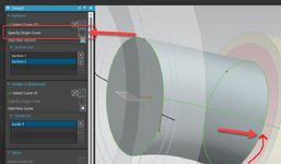
The attached image is the result of an attempt to line up the alignment edges by using patterned planes along the defining spline and splitting the face in two, letting me select two half-circles for the Swept function. Unfortunately, the alignment still ends up wrong (see image).
Thanks in advance,


