Continue to Site

Eng-Tips is the largest engineering community on the Internet

Intelligent Work Forums for Engineering Professionals

  • Congratulations KootK on being selected by the Eng-Tips community for having the most helpful posts in the forums last week. Way to Go!

NX9 section curve 1

Status
Not open for further replies.

Karlis

Mechanical
Jan 8, 2015
79
Hi everyone,
I have been using section curves on a solid body, sewn together from a bunch of sheets.
It is in fact solid because I can use "measure bodies" feature successfully. But the problem I get is that some of the output section curves are not closed. I have been trying to use bounded plane surface on them, some work, some dont. Can anyone suggest me to fight off this problem without going the long way around? And perhaps, a guess why this is happening.
Thanks.
 
Replies continue below

Recommended for you

As for why it may be happening, try running the 'examine geometry' command. Turn on all the face and body checks. Window select around your entire solid body so that the selection picks up all the faces and edges along with the solid body itself. If it fails one of the checks, it may be the cause of your issue.

www.nxjournaling.com
 
Well, interestingly enough, it passed all the "examine geometry" tests. Yet my sections are open.
Could this be somehow connected to the bug I saw back when creating the sheets? For some reason trimmed sheet didnt want to work on one set of faces until I had reduced the tolerance to 0.04. I have assurances that the faces should theoretically meet each other with tolerance close to zero.. But this occurred in a completely different region.
 
While the issue that cowski is providing advice on may be valid for some situations, this will also happen even when your model passes all the tests and so on. What you're seeing is not the result of a bad model or even a model with flaws in it, but rather it's simply how things work, particularly when working with solid bodies created from sewing a series of sheet bodies together to form a 'watertight' body, which the system then tags as being a 'solid' body.

Without going too deeply into the whys and wherefores, lets us just say that when sewing sheets together, even if their edges do not match perfectly, we allow this to work by creating what we call a 'tolerant edge', which gives the impression that there are no gaps due to the fact that there was NOT a perfect fit in the first place. And as far as treating this 'edge' as 'watertight' and the enclosed volumes as solids and the topology of the model as being valid, all of that works AS IF THE EDGES ACTUALLY DID MATCH PERFECTLY. But the reality is that the 'gaps' still exist, just that we ignore them the vast majority of the time and just act as if they don't exist. After all, you can't see them (that's because when we sew two edges together, ONLY one of the edges is left visible so that it looks like they snapped together without any gaps) and when you test the model you're told that the topology is good and when you do mass properties and run tool paths over them or produce FEA meshes, everything works exactly as you would expect it to work if the edges of the model were perfect.

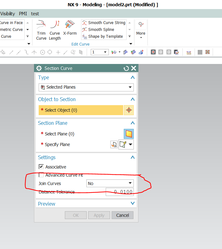
Well I did say the vast majority of the time but one of those functions were we don't automatically treat those 'tolerant edges' as perfect is when creating a 'Section Curve' (there are some good reasons for this but for now, just accept this and move on). But then that's why we included in the 'Section Curve' dialog, in the 'Settings' section, the 'Join Curve' option. You may find it advisable to use this option whenever you're dealing with models created from sewn sheets as this will often be the only way to assure that resulting 'Section' is without gaps. Now the reason that we don't have this ON by default is that whatever you set it to, as long as it's NOT 'No', the resulting curve(s) will be splines. If this set to 'No', then there resulting curves may or may not be splines depending on the type of face being intersected. Analytical faces will produce analytical curves, but there is NO guarantee that they will be created without gaps, even though they are part of the same feature.

Sorry for the long reply, but I think it's important to know why you're seeing what you are and what we've done to provide you with an option to get something usable downstream.

John R. Baker, P.E.
Product 'Evangelist'
Product Engineering Software
Siemens PLM Software Inc.
Digital Factory
Cypress, CA
Siemens PLM:
UG/NX Museum:

To an Engineer, the glass is twice as big as it needs to be.
 
The 'examine geometry' command also has an option to detect tolerant edges, if any are highlighted in an area where you are having trouble with the curves it would verify that they are the cause.

JohnRBaker said:
But then that's why we included in the 'Section Curve' dialog, in the 'Settings' section, the 'Join Curve' option.

I know that the 'project curve' command has a 'join curve' option, but I don't think it exists in the 'section curve' or 'intersection curves' commands. Alternatively, you could try the 'join curve' command after creating the section curves or using 'bridge curve' to bridge the individual gaps. Also, sometimes you can use an 'edge blend' (or 'face blend') to get rid of a tolerant edge, if you don't mind a small blend between the faces in question.

Edit: was not in front on NX when I posted, it IS in the section curve dialog; thanks for the correction, John.
www.nxjournaling.com
 
Yes, the 'Section Curve' function does indeed include the 'Join' option, as shown below:

Section_Curve_with_Join_tpnvin.png


John R. Baker, P.E.
Product 'Evangelist'
Product Engineering Software
Siemens PLM Software Inc.
Digital Factory
Cypress, CA
Siemens PLM:
UG/NX Museum:

To an Engineer, the glass is twice as big as it needs to be.
 
Thanks for the great explanation as always John.
I found that join curve command under section curve options really didnt help this issue, the gaps just appeared in different locations than before.
Despite that, I found a "smooth curve string" command which seems to have been created for exactly this kind of job, but the problem with this is that I get "unable to reference edge" on only one section. It had no gaps before, any ideas? thanks.
I forgot to mention that I get this error when using bounded plane on the generated smooth curve string. It consists of inner and outer circle. Works fine with either circles but not both together. And also, the preview is working just fine, but for some reason it won't create the bounded plane surface.
Upon further investigation I have found that the smooth curve string is not responsible for it, but rather the section curve itself.
 
Instead of creating a 'Bounded Plane' try using 'Extrude' with BOTH limits set to 0.00.

John R. Baker, P.E.
Product 'Evangelist'
Product Engineering Software
Siemens PLM Software Inc.
Digital Factory
Cypress, CA
Siemens PLM:
UG/NX Museum:

To an Engineer, the glass is twice as big as it needs to be.
 
Status
Not open for further replies.

Part and Inventory Search

Sponsor