Continue to Site

Eng-Tips is the largest engineering community on the Internet

Intelligent Work Forums for Engineering Professionals

  • Congratulations KootK on being selected by the Eng-Tips community for having the most helpful posts in the forums last week. Way to Go!

O-ring groove

Status
Not open for further replies.

aniiben

Mechanical
May 9, 2017
158
Based on your individual experience, does anyone know if a gland groove detail should be
defined with GD&T?
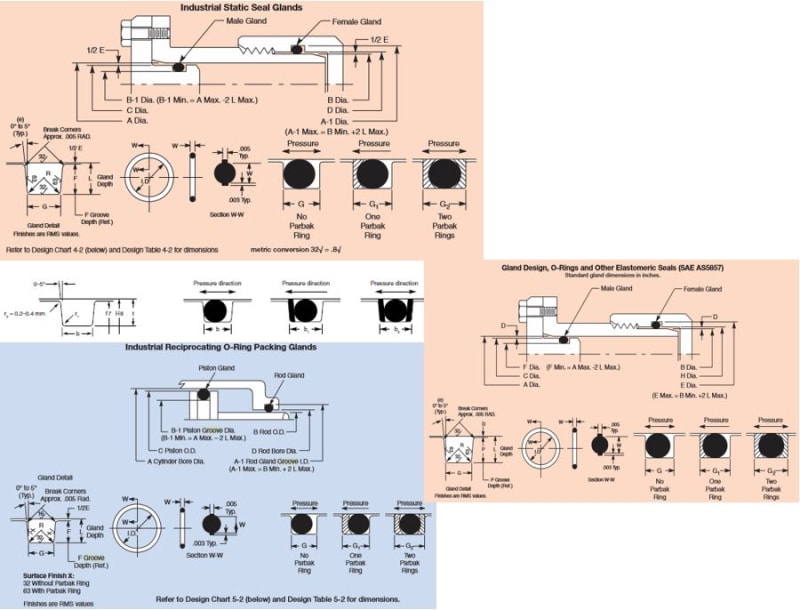
All catalogs found online have angles with plus minus (zero degrees to 5 degrees Typ.) for the sides (groove sides) along with the groove depth and groove width.

How would you GDT this feature?

Does it really need it?

Any feedback will be appreciated (experience, training manuals, books, etc.)

GFQ_-_Copy_zo7gwk.jpg
 
Replies continue below

Recommended for you

Using FCFs is typically valuable when the expected manufacturing variability is a significant portion of the available tolerance for variation. In many areas this is not true; particularly for complex feature elements in common use. For example, o-ring and snap ring grooves, o-rings themselves, and standard screw threads.

Many of these features are created with off-the-shelf tools and machinists are typically sufficiently skilled to produce usable features with them.

While there is something to be said for the certainty that FCFs allow, there hasn't been a significant lack of confidence in the ability to create these features, so there is little motive to add additional checks on them.
 
I'd say profile tolerance if allowed or needed on more critical applications. Many applications (especially low pressure applications) where a few percent less or more of compression doesn't negatively impact the seal could get away with +/- tolerancing. When you get into different materials as well such as metal o-rings there is less margin for error and requires sufficiently more precise tolerancing.
 
Those 0-5 degree side wall angles are completely unimportant and really there for manufacturing convenience. They have no impact on sealing capability because they don't affect squeeze. Don't complicate simple things.

----------------------------------------

The Help for this program was created in Windows Help format, which depends on a feature that isn't included in this version of Windows.
 
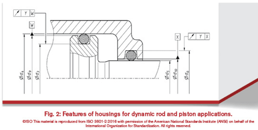
On the illustration shown you can see surface roughness and ISO tolerances for sizes.

I have also seen runout of groove vrt OD routinely specified.

All together should be enough.

"For every expert there is an equal and opposite expert"
Arthur C. Clarke Profiles of the future

 
chez311,

Probably, your proposed profile is to be used when it comes down to risk management, as 3DDave mentioned (undesirable outcomes that have a significant chance of occurring).

How your FCF (s) would looks like in that case?


Runout on the concentric portion of the groove seems worthy of consideration.
 
Capture_ztdzrm.png


"For every expert there is an equal and opposite expert"
Arthur C. Clarke Profiles of the future
 
The runout tolerances in that ISO figure would be a step towards what could be used. With no envelope modifiers (circle E) and no coaxiality controls for the larger and smaller diameter features within each of the two parts, no worst-case boundaries can be found, so the o-ring squeeze range cannot be determined. It also seems odd to me that clearance features are chosen as datum features for both parts. If the inner part moves to the left relative to the outer part a sufficient amount then coaxiality of d5 and the o-ring groove on the inner part (and similar for the outer part) becomes less significant, but what about when the inner part is shifted fully to the right relative to the outer part? Coaxiality of the larger and smaller features on each part then becomes a concern for o-ring squeeze.

Wouldn't it be better to specify d5 as datum feature W and d4 as datum feature X (and also rename "X" to use a better letter, to avoid using X, Y or Z as a datum feature letter)?

With what I think are better choices for datum features along with a combination of size, to control size and form (using ASME Y14.5), and position applied at RFS, to control location and orientation of each o-ring groove cylindrical surface, and also the clearance features then worst case boundaries (I wish we could call them the MMB for each of the features) could easily be determined. From those boundaries the range of o-ring squeeze can easily be determined.

Size and runout tolerances or profile tolerances, as has been pointed out already, could be used too, as long as coaxiality of the cylindrical features within each of the two parts is included.

Another point is that these part may be manufactured by a process other than machining, such as injection molding or 3D printing. Whether a machinist can likely make things good enough doesn't always mean that ambiguous or incomplete tolerances will mitigate risk well enough.

Oh, and Happy Easter to all :)

Dean Watts
 
aniiben,

As chez311 mentioned, a few percent of compression does not matter. Usually the rubber O-ring itself varies vastly in sizes (AS568 standard), so in Parker guide they said compression ratio from 20-30% is ok.
Here is my gland design for AS568-012 O-ring complying to AS 5857 groove standard for facial seal with slight modification according to Parker's guide.
The groove's outer radius is 12.6 H11 (mm).
 
Status
Not open for further replies.

Part and Inventory Search

Sponsor